Dynamic UV-exposure and thermal development of relief image printing elements

a technology of relief image and thermal development, applied in the field of methods, can solve problems such as affecting the quality of finished plates

Inactive Publication Date: 2007-04-19
MACDERMID PRINTING SOLUTIONS
View PDF23 Cites 82 Cited by
  • Summary
  • Abstract
  • Description
  • Claims
  • Application Information

AI Technical Summary

Benefits of technology

[0017] It is an object of the present invention to provide an improved system for creating a relief image printing element that can accomplish multiple steps in the same system.

Problems solved by technology

This requires additional time to transfer the printing element between the separate devices and can affect the quality of the finished plate as a result of handling the printing element.
However, there is no suggestion in Gelbart that the development step can be tied into the same system.

Method used


Image

  • Dynamic UV-exposure and thermal development of relief image printing elements
  • Dynamic UV-exposure and thermal development of relief image printing elements
  • Dynamic UV-exposure and thermal development of relief image printing elements

Examples


Embodiment Construction

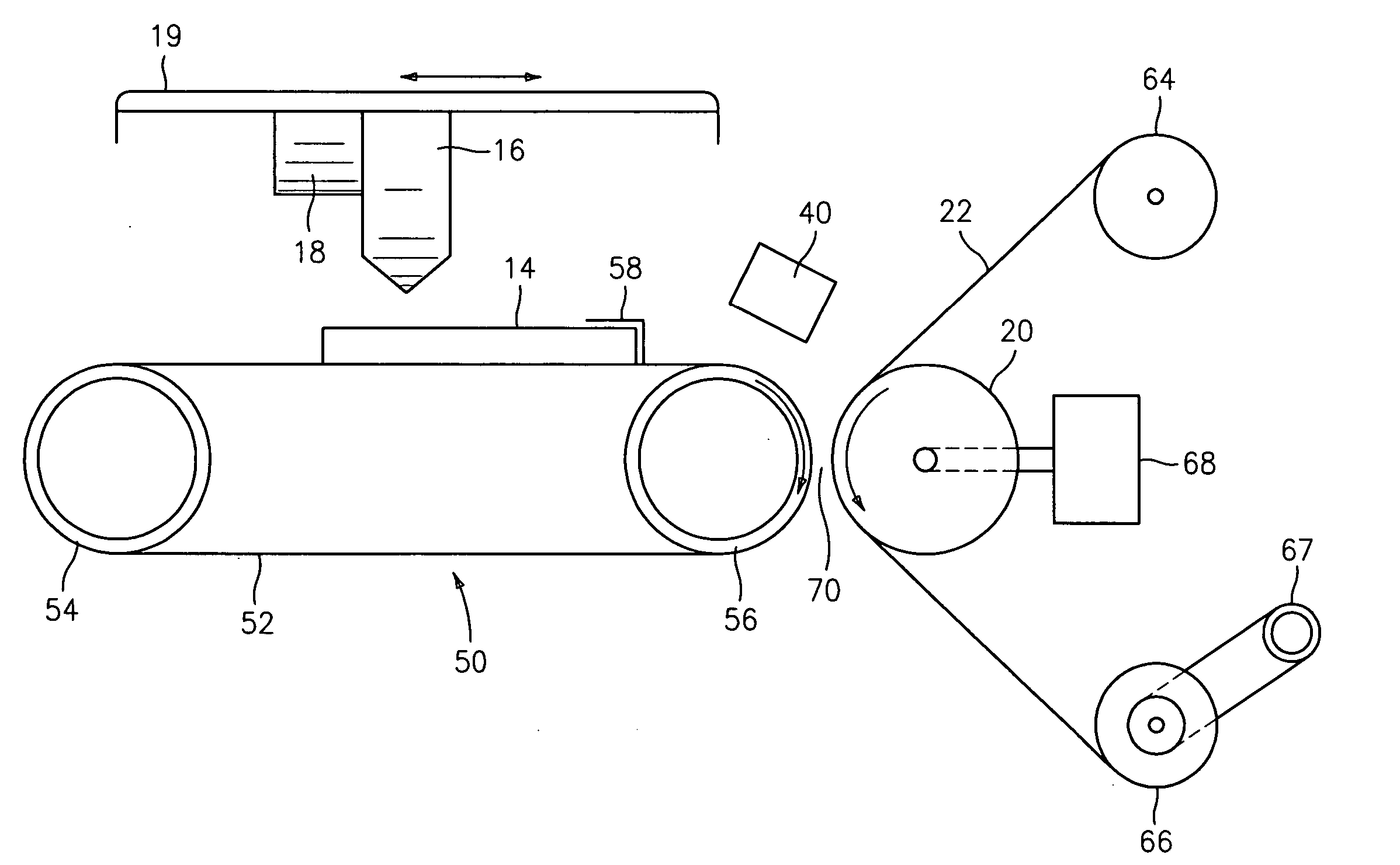
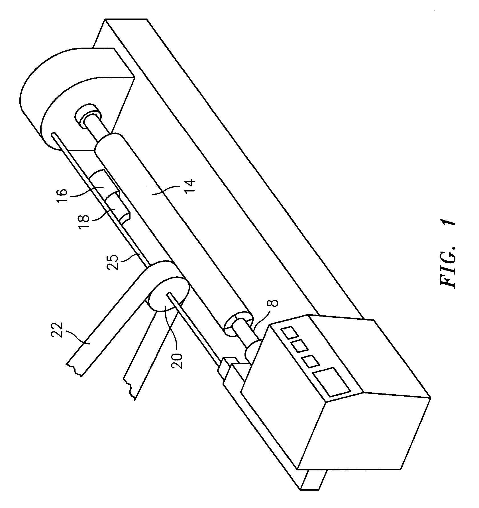
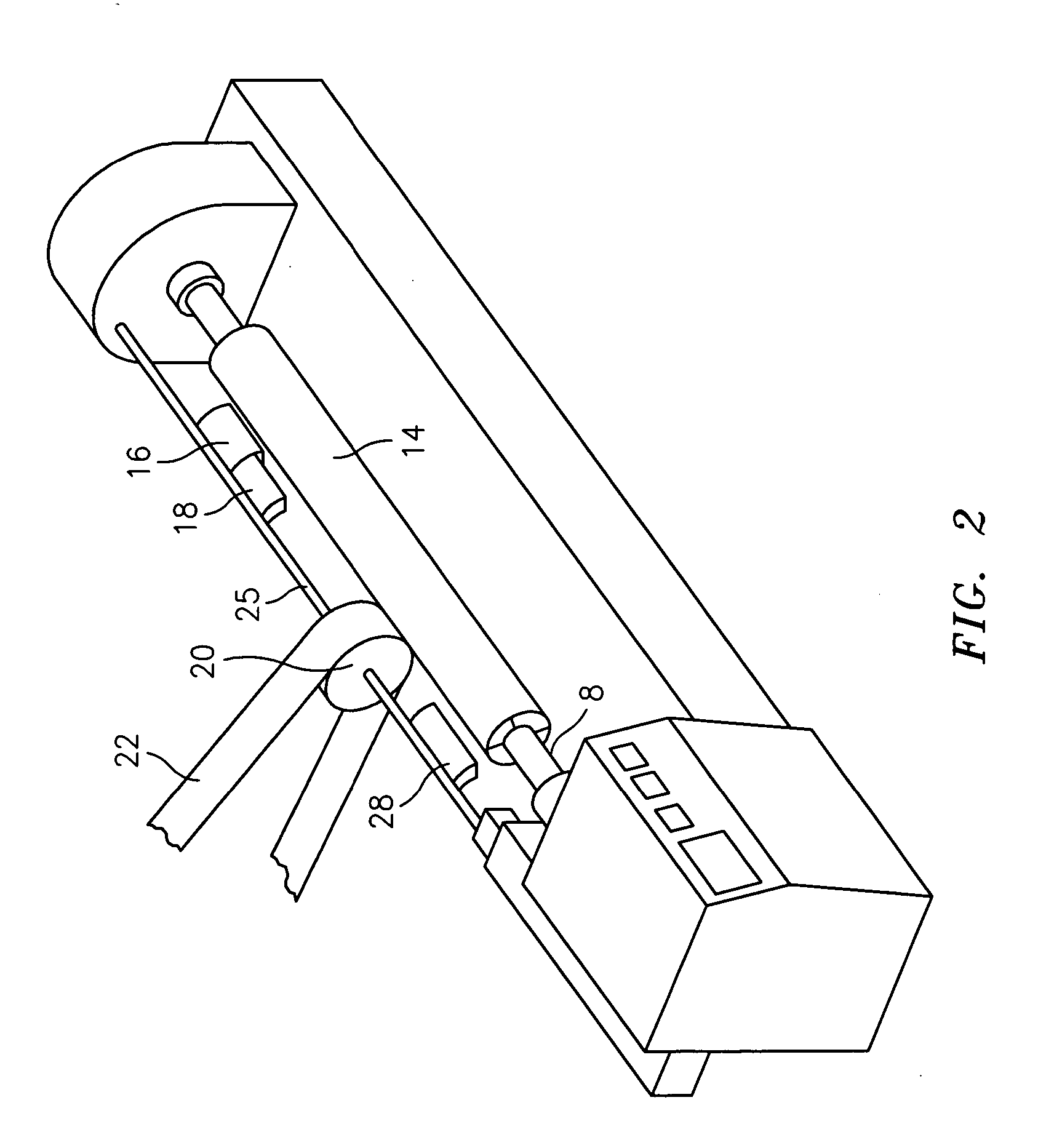
[0036] The present invention relates to an improved system for imaging, exposing and developing a relief image printing element and a method of using the system of the invention to manufacture a relief image printing element.

[0037] The combined system for imaging, exposing and developing a relief image printing element, wherein the relief image printing element comprises at least one photopolymerizable layer on a support, typically comprises:

[0038] means for creating a digitally-imaged mask layer on the at least one photopolymerizable layer of the printing element;

[0039] means for exposing the at least one photopolymerizable layer to actinic radiation through the digitally imaged mask layer to selectively crosslink and cure the at least one photopolymerizable layer; and

[0040] means for thermally developing the printing element to soften and remove non-crosslinked photopolymer and reveal the relief image.

[0041] Prior to processing the printing elements in the combined system of ...


PUM


Abstract

A method and a system for dynamic imaging, UV-exposure and thermal development of relief image printing elements, including printing plates and printing sleeves. The imaging step is accomplished using ink jet printing to create an in situ mask layer on a layer of photocurable material followed by exposing the photocurable layer to actinic radiation through the in situ mask. Thereafter, the printing element is developed in a thermal developing system to create the desired relief image in the surface. If desired, the improved system may also include means for post-exposing/detacking the printing element.

Description

FIELD OF THE INVENTION [0001] The present invention is directed to a method and an apparatus for dynamic imaging, UV-exposure and thermal development of relief image printing elements, including printing plates and printing sleeves. BACKGROUND OF THE INVENTION [0002] Flexography is a method of printing that is commonly used for high-volume runs. Flexography is employed for printing on a variety of substrates such as paper, paperboard stock, corrugated board, films, foils and laminates. Newspapers and grocery bags are prominent examples. Coarse surfaces and stretch films can be economically printed only by means of flexography. Flexographic printing plates are relief plates with image elements raised above open areas. Such plates offer a number of advantages to the printer, based chiefly on their durability and the ease with which they can be made. [0003] Although photopolymer printing elements are typically used in “flat” sheet form, there are particular applications and advantages ...

Claims


Application Information

Patent Timeline
Patent Type & Authority Applications(United States)
IPC IPC(8): B41N1/00
CPCG03F7/2018G03F7/202G03F7/24G03F7/36
Inventor VEST, RYANBIGAOUETTE, RICHARD J.MARKHART, GARY T.
Owner MACDERMID PRINTING SOLUTIONS
Why Eureka
Try Eureka