Flexible solar power module with a current lead integrated in the frame

a solar power module and current lead technology, applied in photovoltaic energy generation, sustainable buildings, photovoltaic energy generation, etc., can solve the problems of not being able to meet building integration requirements, module flexibility is not good, and foil modules are limited in flexibility. , to achieve the effect of not being used for building integration purposes

Inactive Publication Date: 2007-04-19
BAYER MATERIALSCIENCE AG
View PDF11 Cites 49 Cited by
  • Summary
  • Abstract
  • Description
  • Claims
  • Application Information

AI Technical Summary

Problems solved by technology

It is understandable that such modules are not flexible and are subsequently less suitable for building integration by means of a cementing process.
Such foil modules are limited with regard to flexibility.
They are deployed preferably for camping applications and, due to lack of safety against heavy hailstorm, they can also not be used for building integration purposes.
A framing of the laminates is not performed here; moreover, the “solar rolled mechandise” that is usually several meters in length is cemented in the factory onto the roof bands and, with a relatively work-intensive effort, is provided with a rear-side cable connection at least at one location per laminate, and this means an unavoidable breakthrough in the roof covering.
The cementing of the laminates onto the roof bands, which are up to 8 meters in length, is an unfavourable solution in principle because each roof band must be manufactured with individual adaptation (in length and colour etc.) in the factory of the manufacturer for the roof material.
This is not only a consequence of the cementing technique (with a heating table 130° C. and EVA-fusion adhesive) but, above all, is subject to the rear-side electrical connecting configuration that cannot be performed to professional standards on the building as such.
The present BIPV technology as realised, for example, by HOESCH and RHEINZINK with the procurement of flexible UNIsolar® laminates therefore indicates some serious disadvantages: cementing and cable connection is performed in the factory and not on the construction site so th...

Method used


Image

  • Flexible solar power module with a current lead integrated in the frame
  • Flexible solar power module with a current lead integrated in the frame
  • Flexible solar power module with a current lead integrated in the frame

Examples


Embodiment Construction

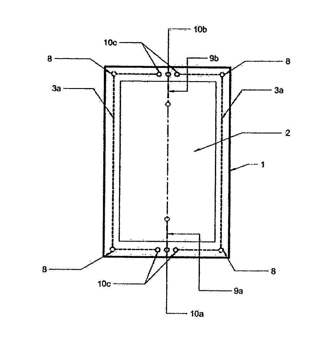
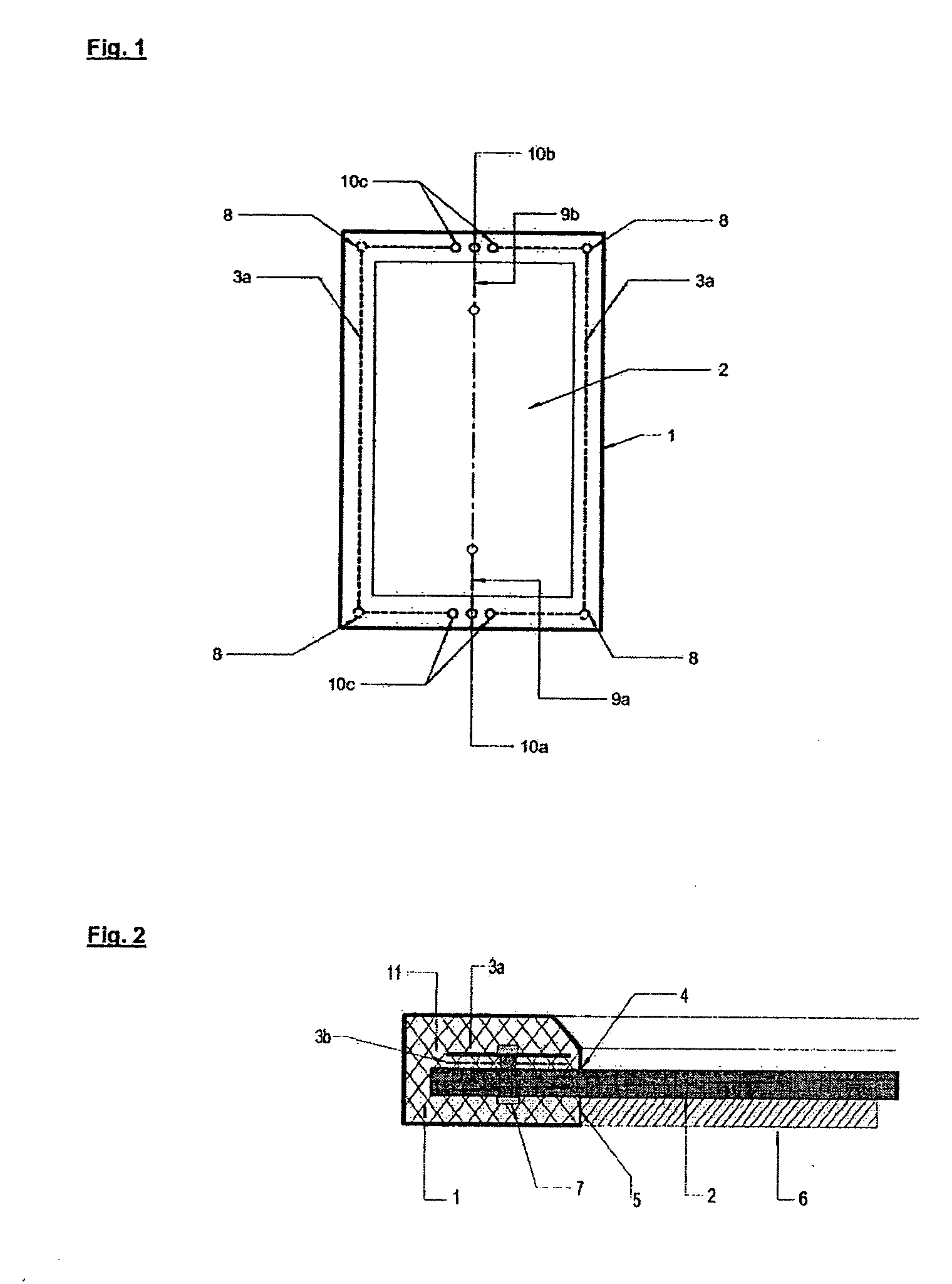
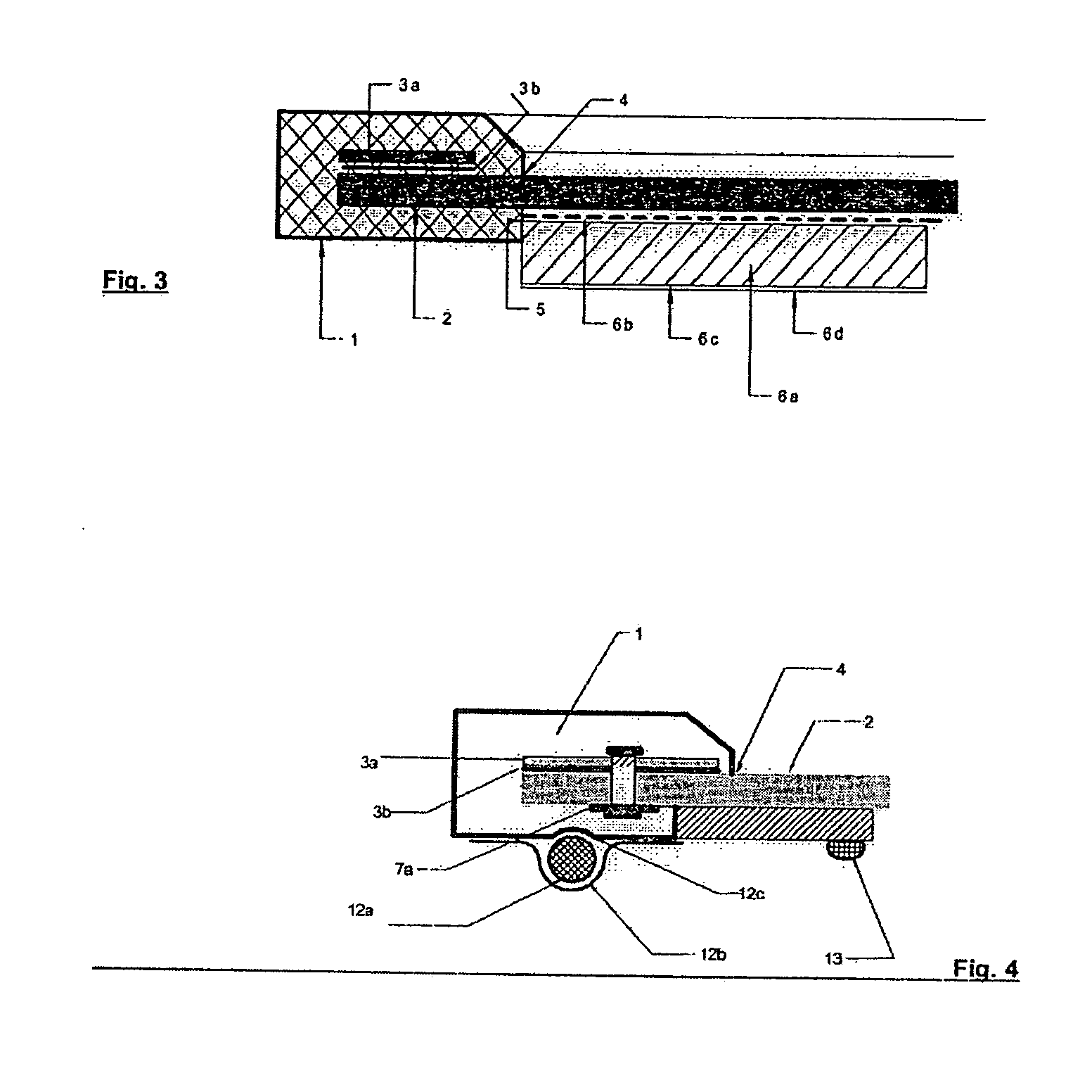
[0051] This invention describes a method nevertheless for the purpose of framing flexible laminates, e.g., of the trademark “UNIsolar®” with a polyurethane by means of RIM-technology. The already mentioned disadvantages of the front-side de-adhesion and the deflection are in fact avoided where the through-wiring consisting preferably of a flat copper band is at first applied to the front side onto the Teflon® foil and is durably joined to the laminate by riveting and / or by a suitable and special cementing.

[0052] The frame on its part sticks securely to the copper band so that the disadvantageous de-adhesion of frame and laminate, as observed without through-wiring, does not occur.

[0053] Furthermore, the rear side of the laminate is provided with a covering before the manufacture of the frame, for example with a foamed or compact synthetic panel. This panel does not shrink or heat up during the framing process, so that there is no disadvantageous deflection of the laminate which oc...


PUM


Abstract

The invention refers to a non-glass and flexible solar power module and the method for its manufacture where the module is provided with a circumferential and flexible frame having integrated through-wiring and socket parts, which are formed face-side into the frame, for module interconnection by means of plug-in connectors. The solar module is thoroughly and completely sealed off on its rear side and has a full-surface smooth texture which is established by the insertion of a thin flexible panel, preferably made of plastic, together with the laminate into the form for the manufacture of the frame by means of RIM (reaction injection moulding). The modules are mounted on the building, preferably by means of bonding/cementing to practically any random roof materials, as well as to curved surfaces and without a backward cable lead.

Description

RELATED APPLICATION DATA [0001] The present application claims priority from prior German patent application 10 2005 032 716.8, filed Jul. 7, 2005, incorporated by reference herein in its entirety. BACKGROUND OF THE INVENTION [0002] Well over 90% of all solar power modules produced at present consist of “solar cells” which are covered off on one side with a pane of glass, on the other side with a special synthetic foil or with a further pane of glass. Such an embedding of solar cells is known as “laminate”. Provided with a frame that usually consists of aluminium profile in conjunction with a rear-side electrical connection, the laminate is transformed into the commercially available final product, a “solar module”. It is understandable that such modules are not flexible and are subsequently less suitable for building integration by means of a cementing process. [0003] The term “foil module” designates the embedding of solar cells between two synthetic foils, and if required between...

Claims


Application Information

Patent Timeline
IPC IPC(8): H02N6/00H02S30/20
CPCY02B10/12H02S20/00Y02E10/50H02S20/22Y02B10/10H02S30/10
Inventor KALBERLAH, KLAUSSCHLEMPER, KLAUSEHBING, ING. HUBERTSCHAUSEIL, FRANK
Owner BAYER MATERIALSCIENCE AG
Why Eureka
Try Eureka