Method of launching a catapult, catapult, and locking device

Active Publication Date: 2007-04-19
ROBONIC
View PDF5 Cites 15 Cited by
  • Summary
  • Abstract
  • Description
  • Claims
  • Application Information

AI Technical Summary

Benefits of technology

[0015] The essential idea of an embodiment of the invention is to adjust the maximum of the damping force on the basis of the laun

Problems solved by technology

Acceleration peaks may exceed the maximum allowed accelerat

Method used


Image

  • Method of launching a catapult, catapult, and locking device
  • Method of launching a catapult, catapult, and locking device
  • Method of launching a catapult, catapult, and locking device

Examples


Embodiment Construction

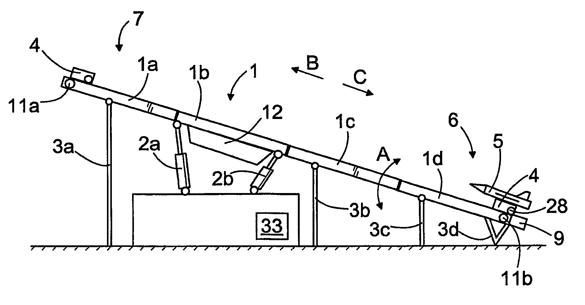
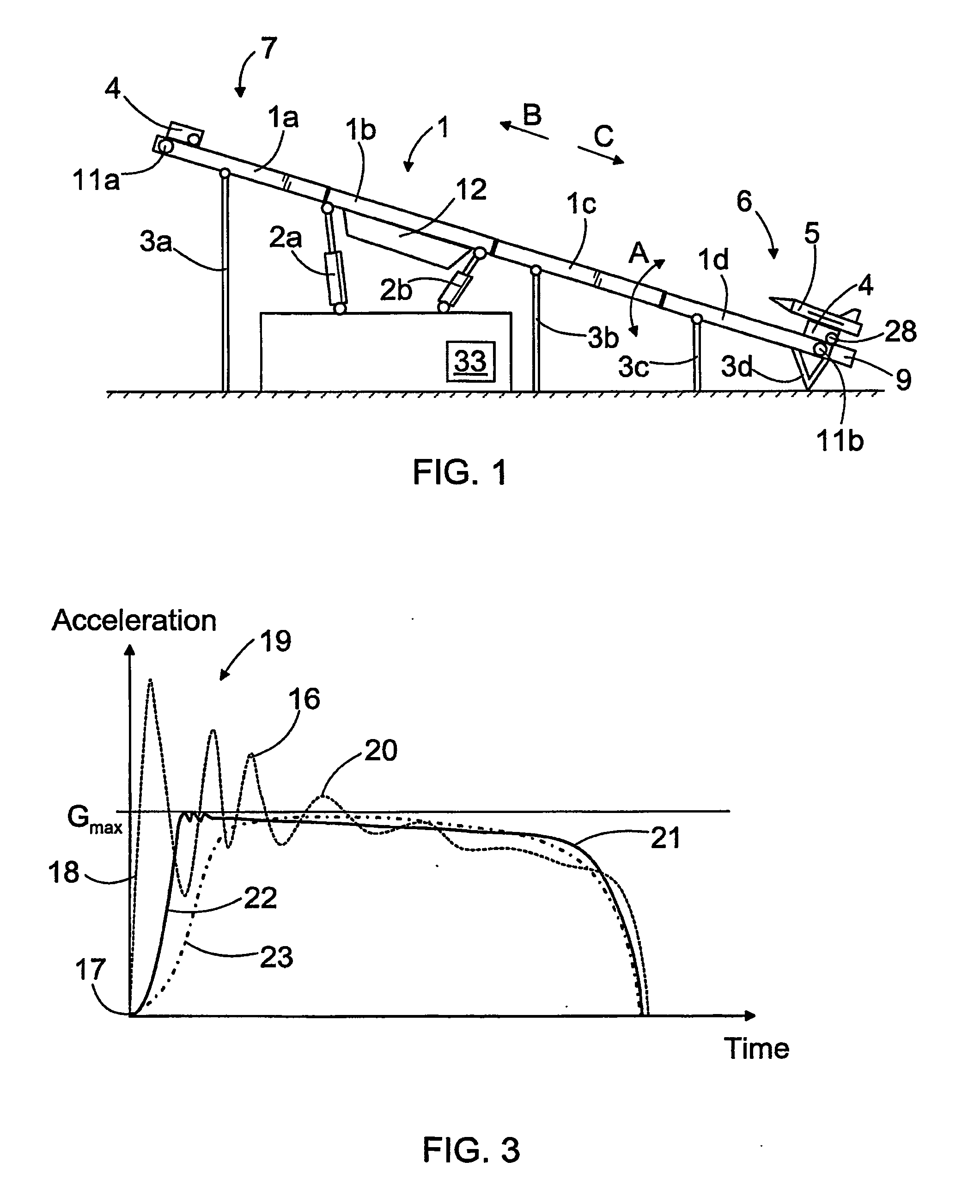
[0025]FIG. 1 shows a catapult in a launching position. The catapult comprises an elongated body 1, which may be composed of several body portions 1a to 1d. The body 1 can be lifted and lowered for instance with hydraulic cylinders 2a and 2b so as to achieve the desired launching angle A. In addition, the body 1 can be supported with a suitable number of supports 3a to 3d. The catapult further comprises a carriage 4 having fastening members for fastening an aircraft 5. The carriage 4 may be supported on guiding surfaces or corresponding support surfaces provided in the body 1 by means of rollers, slide blocks or corresponding members. In the portion of a first end of the body 1 is provided a launching position 6 and in the portion of a second end is provided a releasing position 7. The carriage 4 is movable with high acceleration from the launching position 6 to the releasing position 7, where the aircraft 5 is released from the carriage and takes off. The aircraft 5 may be released ...


PUM


Abstract

A method of launching a catapult, a catapult and a locking device for a catapult. The catapult comprises a carriage (4) for fastening an aircraft (5). The carriage (4) can be provided with a high acceleration by directing a launching force (F1) generated by a launching device thereto. The carriage (4) can be held at a launching position (6) by means of the locking device (9). The catapult further comprises a takeoff damper (34) that generates a damping force (F2) having a direction opposite relative to the launching force. Accordingly, the takeoff damper (34) restricts the acceleration of the carriage (4) at the initial launching moments.

Description

BACKGROUND OF THE INVENTION [0001] The invention relates to a method of launching a catapult, the method comprising: generating a launching force by means of a launching device; keeping a carriage immovable by means of a locking device at a launching position of the catapult; directing the launching force to the carriage, which is movable from the launching position to a releasing position guided by a body of the catapult; releasing the locking device at a launching moment, whereby the carriage moves towards the releasing position at an accelerating speed by the action of the launching force; and sending off an aircraft arranged in the carriage to the air at the releasing position. [0002] The invention further relates to a catapult for launching an unmanned aircraft and comprising: an elongated body, a launching position being provided on a portion of a first end thereof, and a releasing position being provided on a portion of a second end thereof; a carriage movable from the launch...

Claims


Application Information

Patent Timeline
IPC IPC(8): B64F1/04B64F1/06F41B3/02F41F3/04F41F7/00H05B3/84
CPCF41B3/02F41F3/0406F41F7/00
Inventor LIPPONEN, PENTTI
Owner ROBONIC
Why Eureka
Try Eureka