
Dual stage hybrid inflator

a hybrid inflator and dual stage technology, applied in the direction of vehicle components, pedestrian/occupant safety arrangements, fastening means, etc., can solve the problems of destroying the housing, children, small adults, or adults out of position, and interacting with the airbag, and achieve the effect of rapid full filling of the airbag

Inactive Publication Date: 2007-04-19
KEY SAFETY SYST
View PDF16 Cites 43 Cited by
  • Summary
  • Abstract
  • Description
  • Claims
  • Application Information

AI Technical Summary

Benefits of technology

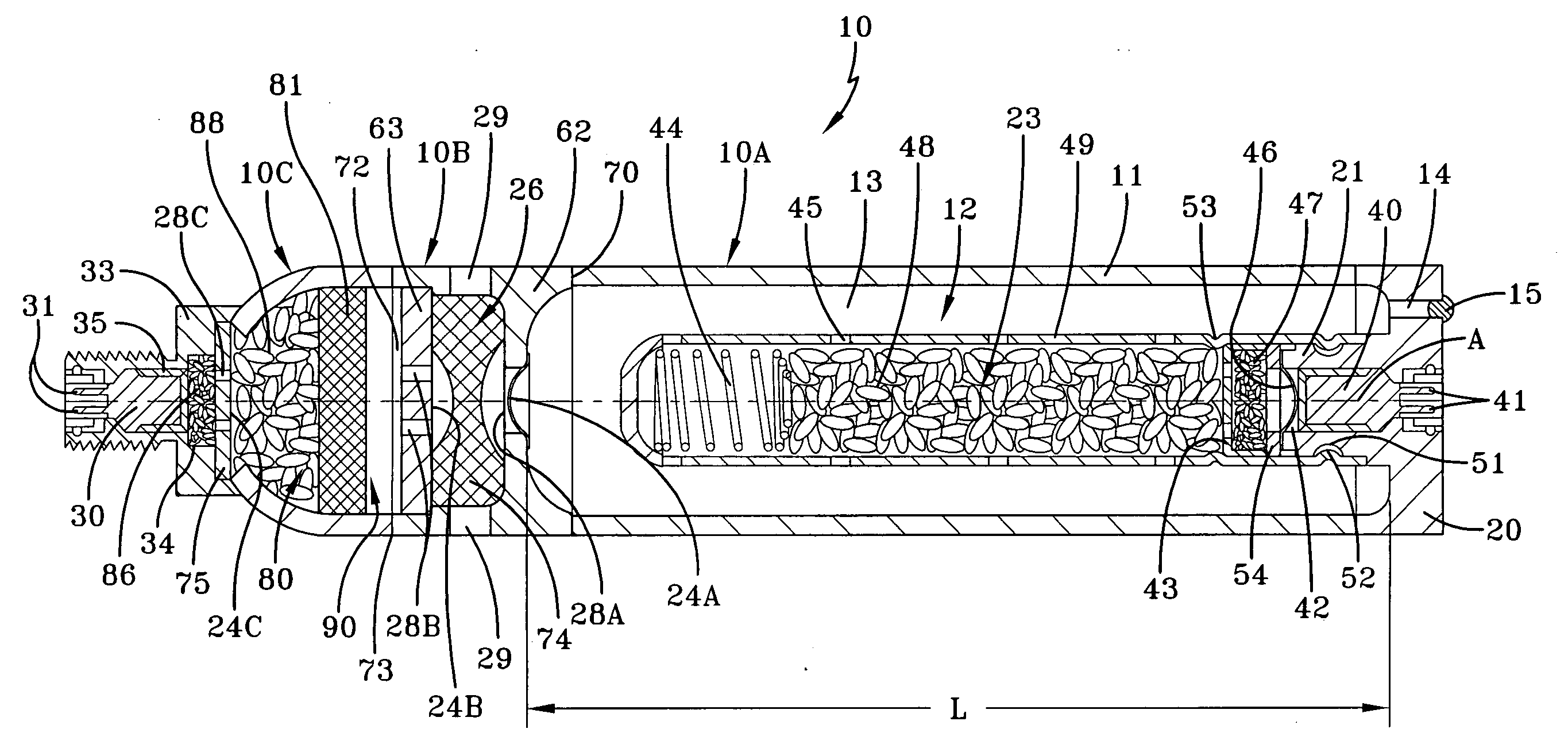
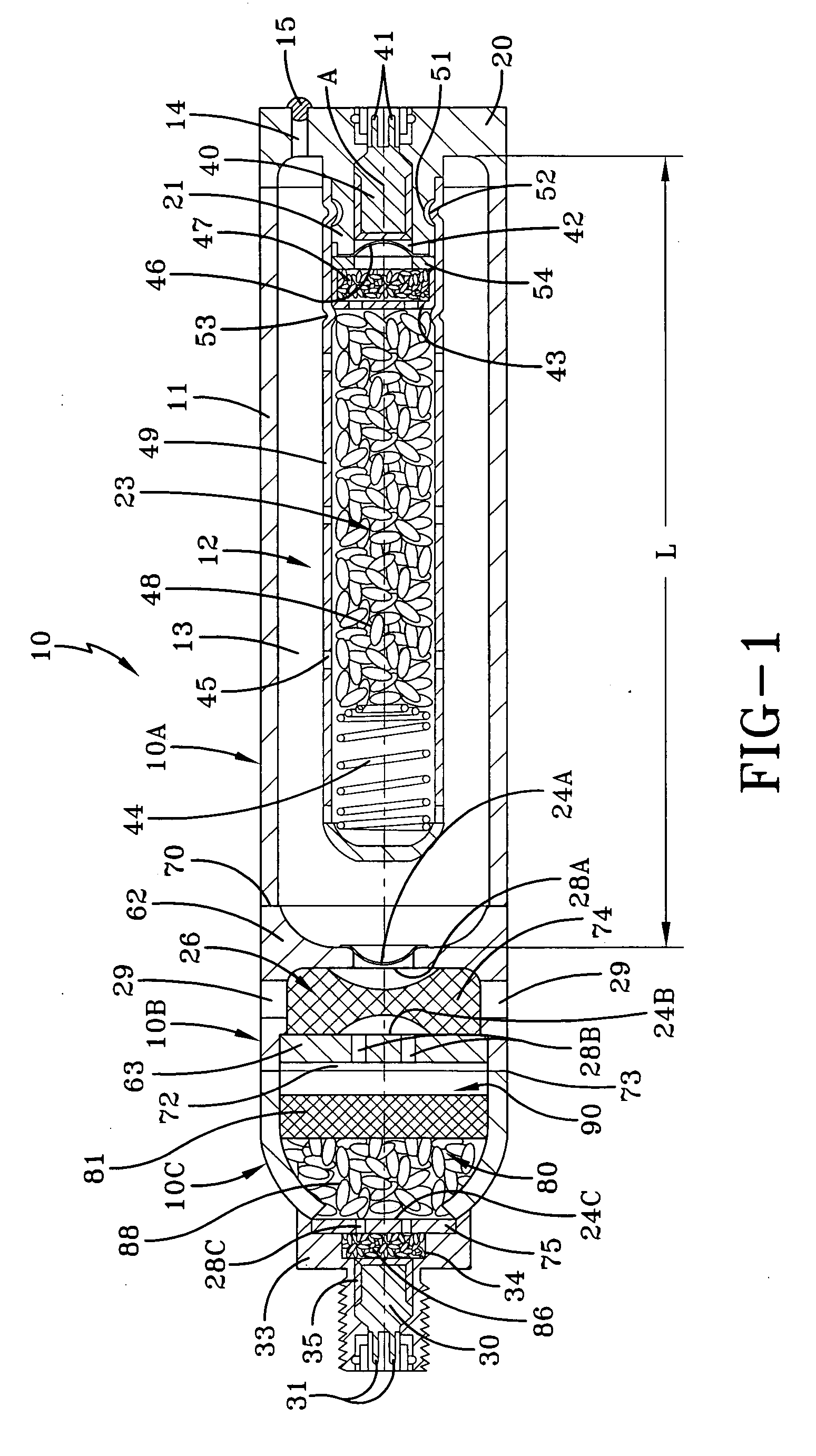
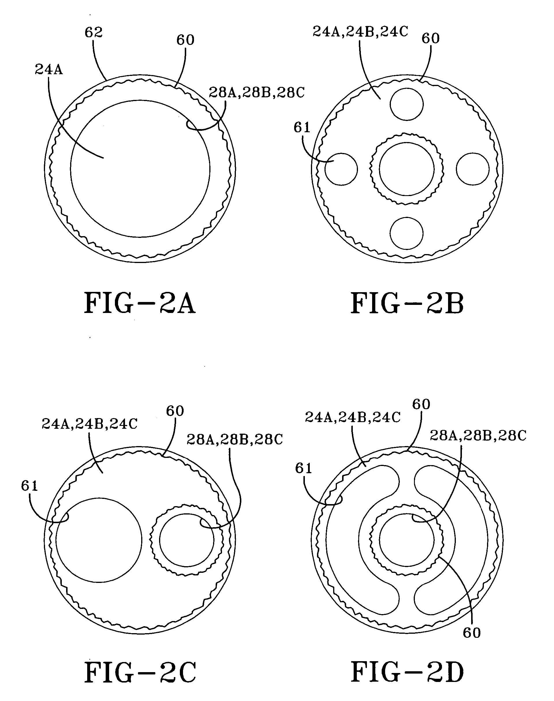
[0039] The primary advantage of the present invention is that the time delays possible are greatly increased by the fact that the inflator has separate gas generating sources. One gas generating source combined with pressurized charge of inert gas the other gas generating source separate from and isolated from the pressure vessel. A key advantage of the present invention is the ignition of one gas generator subassembly will not cause the other gas generator subassembly to ignite. The sizing of the discharge openings 28A, 28B, 28C and 61 and the large exhaust openings 29 are designed to insure the internal pressures are quickly vented to fill the airbag avoiding a secondary undesired ignition. Only by igniting both igniters will both the charges ignite and thus ignition can be simultaneously timed or sequentially triggered as desired.

Problems solved by technology

The problem associated with aggressive airbag deployment is the possibility of a child, a small adult, or an out of position adult interacting with the airbag while it is being inflated.
U.S. Pat. No. 6,557,890 relies on a piston (plug) to separate the ignition gas from the compressed gas which according to the Japanese references is very difficult to move causing unusual pressure rises internal to the inflator which may destroy the housing.

Method used


Image

  • Dual stage hybrid inflator
  • Dual stage hybrid inflator
  • Dual stage hybrid inflator

Examples


Embodiment Construction

[0016] The present invention provides a dual stage inflator 10 able to gently inflate an automotive airbag so as not to injure an out of position child or small adult while still being capable of providing crash protection to a full size adult. The dual stage inflator 10 provides various output levels of inflation gas for inflating an airbag usable with a vehicle occupant restraint system. The dual stage inflator 10 comprises a cylindrical elongated outer housing 11 forming a pressure vessel 12 in a first portion 10A that is filled with stored gas 13, which is released from the inflator during a crash to inflate a vehicle airbag. The dual stage inflator 10 has a generally cylindrical shape and may be formed of stainless steel, low carbon steel, or any other suitable material, which has sufficient strength and extremely low gas permeability.

[0017] The ideal characteristics for the stored gas 13 are that the gas is inert, is not highly temperature sensitive, and is capable of inflati...


PUM


Abstract

An inflator for an airbag has a cylindrical housing forming a pressure vessel for storing inert gas within a first end portion; a second end portion forming a separate combustion chamber, and an intermediate diffusion portion interposed between the first and second end portions for exhausting gases from the inflator into an airbag. The inflator has a first gas generator subassembly disposed within the first end portion and in communication with the stored inert gas. A second gas generator subassembly has a combustion chamber which is disposed within the second end portion and isolated from the inert gas by one or more rupturable sealing disks. The actuation of the inflator can be accomplished such that one or both of the gas generators can be ignited. The ignition can be simultaneously or sequential permitting either very rapid full filling of the airbag or slower prolonged filling.

Description

FIELD OF THE INVENTION [0001] The present invention relates generally to a device for inflating an airbag and more specifically to a dual stage inflator capable of providing various levels of inflation. BACKGROUND OF THE INVENTION [0002] Inflatable restraints or airbags have been shown to reduce the seriousness of vehicle occupant injury during a vehicle crash. An airbag, filled with inflation gas, provides a cushion between a vehicle occupant and the instrument panel or steering wheel. The likelihood of injury is minimized by the airbag absorbing some or all of the kinetic energy associated with the vehicle occupant during a crash. [0003] An inflator provides the inflation gas utilized to inflate an airbag. Inflators generally provide inflation gas by burning a pyrotechnic material, releasing stored gas, or by some combination thereof. During a crash, the inflator is actuated to rapidly inflate an airbag. Aggressive airbag deployment has the advantage of getting the inflated airbag...

Claims


Application Information

Patent Timeline
Patent Type & Authority Applications(United States)
IPC IPC(8): B60R21/26
CPCB60R21/272B60R2021/2633B60R21/261B60R2021/26076F16B5/08
Inventor KELLEY, MICHAELMULVILLE, MICHAELHOSEY, EDWARDCURTIS, ANTHONY
Owner KEY SAFETY SYST
Learn More