Light mixing plate and direct backlight module

a backlight module and mixing plate technology, applied in the field of backlight modules, can solve the problems of affecting the brightness of the backlight module, and ccfls mercury is considered a hazard to the environment protection, and is legally prohibited, and achieves the effect of improving brightness

Inactive Publication Date: 2007-04-19
RADIANT OPTO ELECTRONICS
View PDF7 Cites 182 Cited by
  • Summary
  • Abstract
  • Description
  • Claims
  • Application Information

AI Technical Summary

Benefits of technology

[0024] Additionally, the V-shaped light guiding entities could be configured along both the first and the second surfaces, and the orientation of the V-shaped light guiding entities on these two surfaces are orthogonal to achieve multi-directional focusing and thereby an even better brightness.

Problems solved by technology

However, the mercury contained inside the CCFLs is considered a hazard to the environmental protection and is legally prohibited in the use of goods by many advanced countries.
This inevitable makes the backlight module quite thick, which is not conforming to the market's requirement for slim LCDs.
This technique is effective but only to a limited extent.

Method used


Image

  • Light mixing plate and direct backlight module
  • Light mixing plate and direct backlight module
  • Light mixing plate and direct backlight module

Examples


Embodiment Construction

[0041] The following descriptions are of exemplary embodiments only, and are not intended to limit the scope, applicability or configuration of the invention in any way. Rather, the following description provides a convenient illustration for implementing exemplary embodiments of the invention. Various changes to the described embodiments may be made in the function and arrangement of the elements described without departing from the scope of the invention as set forth in the appended claims.

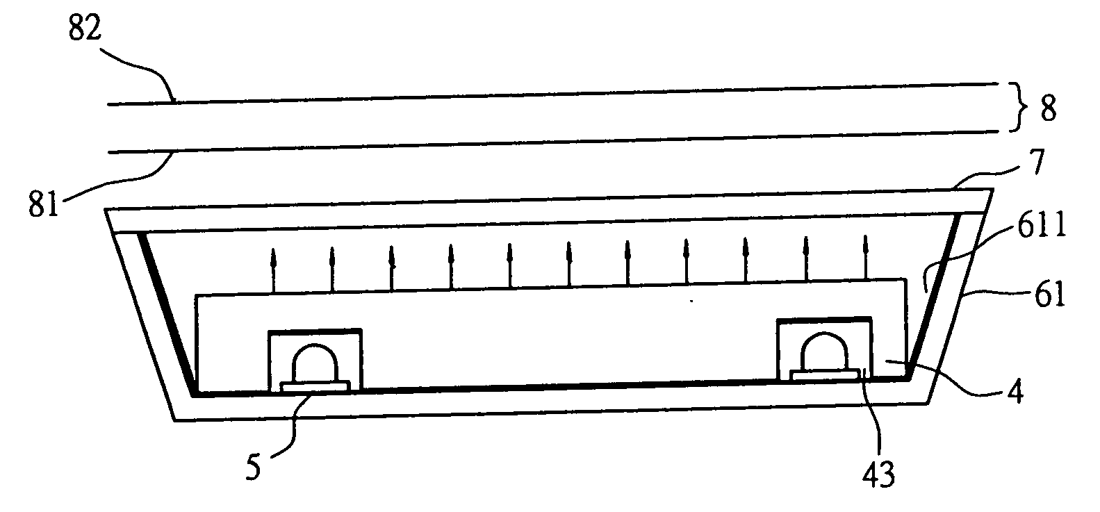
[0042] As shown in FIG. 6, a light mixing plate 4 according to an embodiment of the present invention, made of a material having a high transparency such as Polymethyl Methacrylate (PMMA), has a first surface 41 and a second surface 42. Along the first surface 41, there are a number of elongated grooves 43 indented into the first surface 41 but not penetrating to the second surface 42. The cross-section of the grooves 43 could have a rectangular or other appropriate shape.

[0043] As shown in FI...


PUM


Abstract

A novel light mixing plate and a direct backlight module using the light mixing plate are provided herein. The light mixing plate has a first surface and a second surface, in which a number of indented grooves are configured along the first surface to accommodate the LED light sources. The lights from the LEDs enter the light mixing plate via the side walls of the grooves and propagate an extended distance inside the light mixing plate so that they are fully mixed with each other into a uniform planar white light when leaving the light mixing plate via the second surface.

Description

BACKGROUND OF THE INVENTION [0001] (a) Technical Field of the Invention [0002] The present invention generally relates to backlight modules and, more particularly, to a light mixing plate and a backlight module utilizing the light mixing plate. [0003] (b) Description of the Prior Art [0004] Currently, most large-sized liquid crystal displays (LCDs), such as LCD monitors, LCD TVs, etc., adopt a direct backlight module. As illustrated in FIG. 1, a conventional direct backlight module mainly contains a number of light source units 12 positioned inside a casing 11, a diffusion plate 13, and one or more optical sheets 14. [0005] The inner surface of the casing 11 is coated with a reflection film 11, or is processed to reflect lights from the light source units 12. [0006] Usually, cold cathode fluorescent lamps (CCFLs) are used as the light source units 12, which are arranged uniformly inside the casing 11. [0007] The diffusion plate 13 is positioned in front of the light source units 12 ...

Claims


Application Information

Patent Timeline
Patent Type & Authority Applications(United States)
IPC IPC(8): G01D11/28
CPCG02B6/0021G02B6/0036G02B6/0038G02F1/133603G02F1/133609G02F1/133611
Inventor CHEN, WEI HSUANLIN, YI FANG
Owner RADIANT OPTO ELECTRONICS
Why Eureka
Try Eureka