
Medical imaging system and anti-collision method with a controllable arm

a technology of medical imaging and controllable arms, applied in the field of medical imaging systems, can solve the problems the patient, the possibility of a collision between the moveable parts, such as the robot arm, and the patient, and achieve the effect of a faster, more precise and simple anti-collision system

Active Publication Date: 2007-04-19
SIEMENS HEATHCARE GMBH
View PDF13 Cites 46 Cited by
  • Summary
  • Abstract
  • Description
  • Claims
  • Application Information

AI Technical Summary

Benefits of technology

[0011] The object underlying the invention is to provide a medical imaging system with a faster, more precise and simpler anti-collision system, as a well as a corresponding anti-collision method.
[0014] The control device advantageously calculates the distances of the moveable part from the surface of the patient or another object lying in the traversing path from the detected surface of the patient, and correspondingly controls the movement. To this end, the at least one sensor transmits the positions of individual surface areas of the patient or another object to the control device and at the same time the control device continuously determines the position of the moveable part and stores this position and / or obtains the position of the moveable part from a second sensor which detects the position of the moveable part and transmits it to the control device. The control device can then determine the distances between the moveable part and the corresponding surface areas from the positions and can correspondingly control the speed and / or the direction of motion of the moveable part.
[0015] The sensor for determining the surface areas can be an ultrasound sensor, an optical sensor or an electromagnetic sensor. In particular, sensors based on contact are not used as in the prior art, but instead sensors which can already locate and specify an approximation between a sensor-equipped system component such as for instance the moveable part and external objects such as the patient from the distance. Such sensors are particularly advantageous for rapid movements, such as for instance in the case of 3D acquisition.
[0019] The coordinate system of the imaging system and that of the sensor or of the sensors are advantageously spatially calibrated in respect of each other. This allows the control device to calculate the distances between the moveable part and the surface areas of the external object, such as for instance the surface of the patient. Furthermore the imaging system can also be designed to create a 3D model of the patient from the detected surface of the patient and to register this with the coordinate system of the imaging system. In this case, the control device can predetermine the movement of the moveable part precisely. This 3D model is advantageously updated at regular intervals, in order to avoid a false 3D model forming the basis of the projections of the control device with the movements of the patient. All calculations can also be carried out by an external computing unit, which supplies the results to the control device.

Problems solved by technology

One problem with this type of imaging system with moveable parts thus consists in the possibility of a collision of the moveable parts with the patient.
The risk here is the possibility of a collision of the moveable part, such as for instance the robot arm, with the patient.
The risk of a collision between this support arm and the patient or the support arm and another mechanical component such as the table for instance and a second support arm or other medical devices particularly exists with fast movements of mechanical support arms.
With patients of low weight in particular, this protective zone is thus often remote from the actual patient surface.
It thus often takes an unnecessarily long time to run a specific angulation of the C-arm.
These sensors nevertheless only have a minimal coverage, so that the intention here is to slow down the movement of the C-arm when entering an accepted protective zone, as rapid movements can otherwise result in a collision.
One disadvantage with the mechanical design of an anti-collision method or the calculation of a protective zone is that the method is either based on contact or requires significant computing effort, so that with increasingly faster movements of the moveable part, the response time, which is hereby ever shorter, is often insufficient to actually prevent a collision, and / or increasingly higher braking pulses are needed to intercept the moveable part.
This in turn requires steadier and more powerful motors and / or braking systems, which in turn increases the costs and the dimensions or the systems, whereby the braking pulses and the course of motion of the moveable part is finally once again negatively influenced.

Method used


Image

  • Medical imaging system and anti-collision method with a controllable arm
  • Medical imaging system and anti-collision method with a controllable arm
  • Medical imaging system and anti-collision method with a controllable arm

Examples


Embodiment Construction

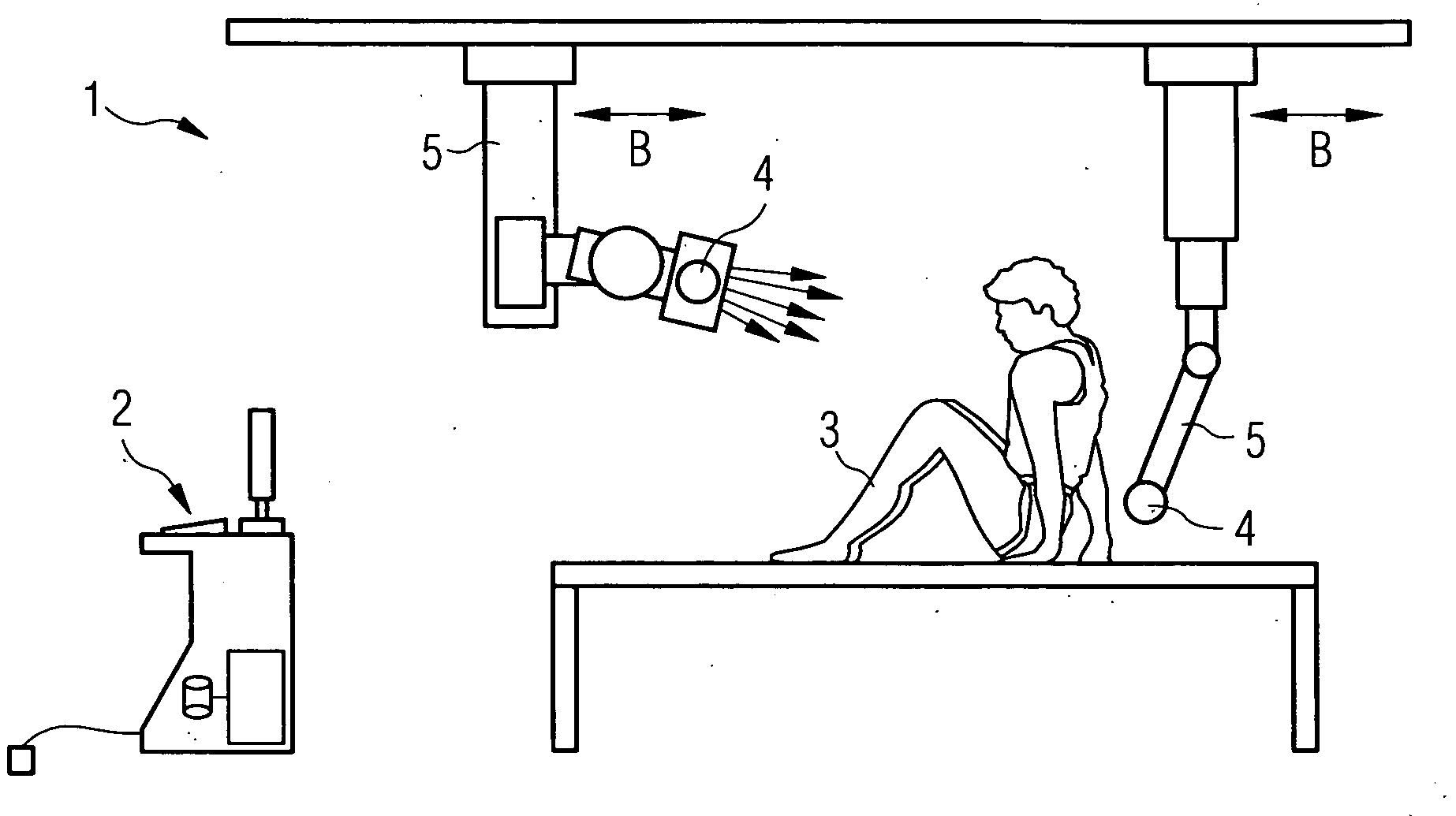
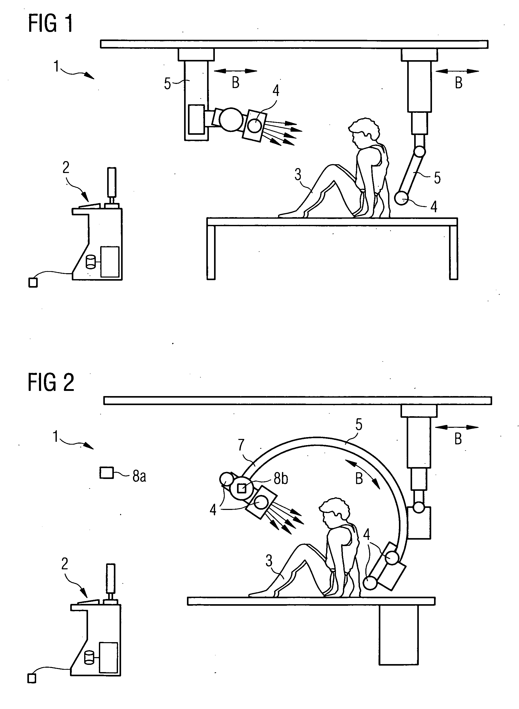
[0026]FIG. 1 shows a medical imaging system 1 with a schematically illustrated patient 3, which is positioned on a table. A 3D stand for the x-ray emitter (depicted in the left of the image) and a 3D stand for the x-ray detector are positioned on both sides of the patient, so that fluoroscopy recordings of the lungs of the patient can be produced for instance. For adjustment purposes, both stands can be moved in the direction of motion B or vertically thereto. Furthermore, the x-ray detector can be rotated. This moveable part 5 is provided with a sensor 4, and, similarly to the x-ray emitter, is also equipped with a sensor 4. The two sensors 4 allow corresponding distances between the moveable parts 5 and the surface of the patient 3 to be detected, and transmitted to a control device 2, which controls the movement B of the moveable parts 5.

[0027]FIG. 2 shows an x-ray C-arm system, for cardiology or angiography for instance, with sensors 4 on correspondingly exposed points of the x...


PUM


Abstract

The invention relates to a medical imaging system as well as an anti-collision method for the like. With this, the movement of a moveable parts, e.g. a C-arm is stopped or slowed down if the part approaches the patient, i.e. falls below a predeterminable minimal distance to specific surface areas of the patient or approaches these. These distances are detected by means of at least one sensor.

Description

CROSS REFERENCE TO RELATED APPLICATIONS [0001] This application claims priority of German application No. 10 2005 049 106.5 filed Oct. 13, 2005, which is incorporated by reference herein in its entirety. FIELD OF THE INVENTION [0002] The invention relates to a medical imaging system with a part which can be moved about a patient and in particular a system, in which the movement of the moveable part is controlled by means of a control device, which stops or slows down the movement, if the part approaches the patient, i.e. it falls below a predeterminable minimal distance to specific surface areas of the patient or approaches these. BACKGROUND OF THE INVENTION [0003] In the prior art, medical imaging system, in particular x-ray systems, are known, which are characterized by extensive flexibility in the movements of the image recording devices about the patients. In the case of an x-ray system, these moveable parts are in particular the x-ray detector and the x-ray tube. The so-called ...

Claims


Application Information

Patent Timeline
IPC IPC(8): H05G1/54
CPCA61B5/0064A61B5/1114A61B6/102A61B6/4441A61B6/4458A61B6/547A61B6/589A61B6/548A61B6/4452A61B6/4464
Inventor SPAHN, MARTIN
Owner SIEMENS HEATHCARE GMBH
Features
  • Generate Ideas
  • Intellectual Property
  • Life Sciences
  • Materials
  • Tech Scout
  • Unparalleled Data Quality
  • Higher Quality Content
  • 60% Fewer Hallucinations
Learn More