Optical fiber array

a technology of optical fiber array and optical fiber, applied in the field of optical fiber array, can solve the problems of more serious problems, more and more demanding communication speed and bandwidth of electronic devices, etc., and achieve the effect of easy cutting in desired shap

Inactive Publication Date: 2007-04-19
WENG ALLEN
View PDF1 Cites 8 Cited by
  • Summary
  • Abstract
  • Description
  • Claims
  • Application Information

AI Technical Summary

Benefits of technology

[0009] Moreover, lens is directly formed on bottom side of fiber base and the fiber is embedded into container formed in front of the lens. The relative position between the fiber array and lens are fixed and not changed with temperature. The base i

Problems solved by technology

As rapid progress of communication technology, the communication speed and bandwidth are more and

Method used


Image

  • Optical fiber array
  • Optical fiber array
  • Optical fiber array

Examples


Embodiment Construction

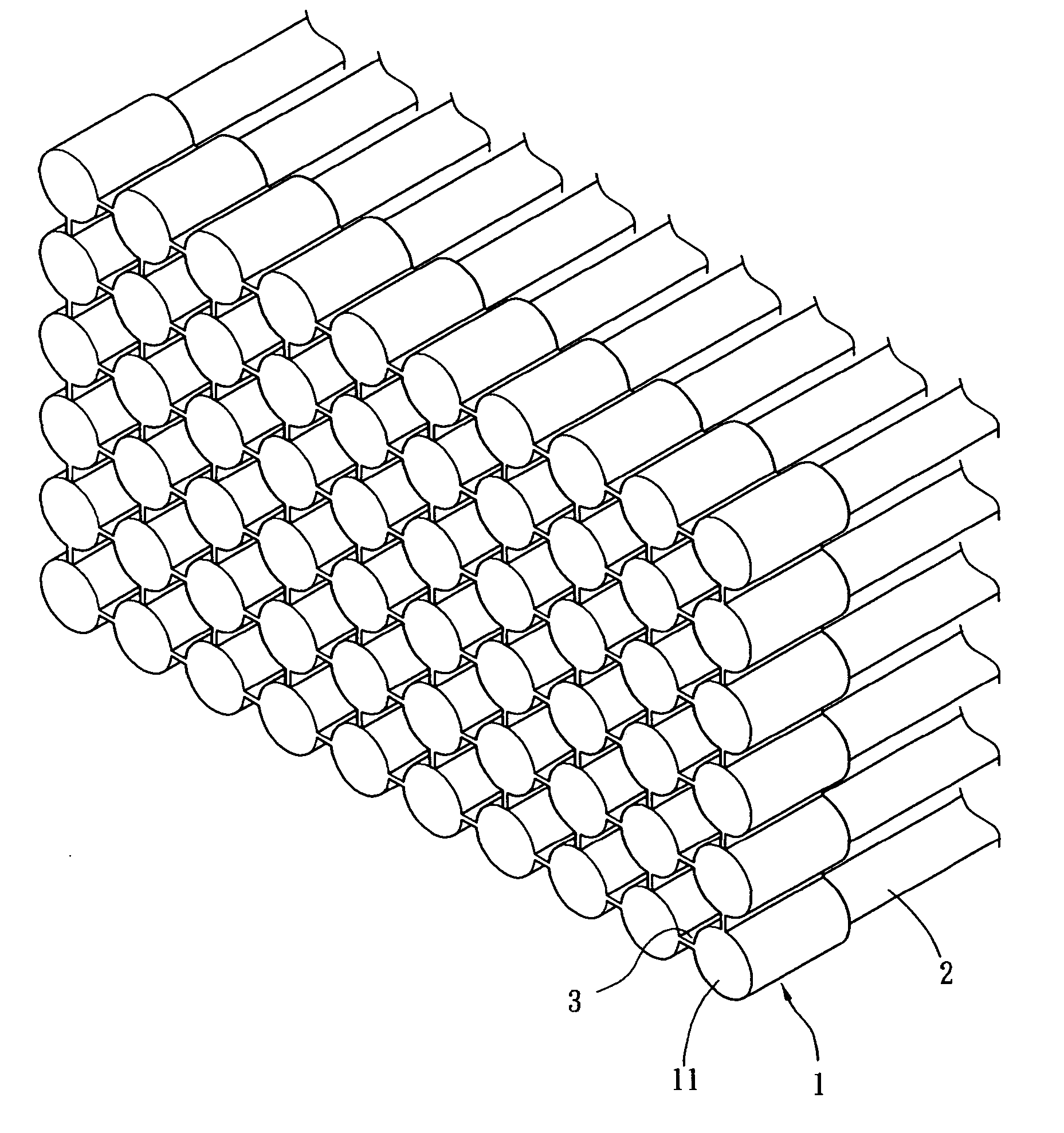
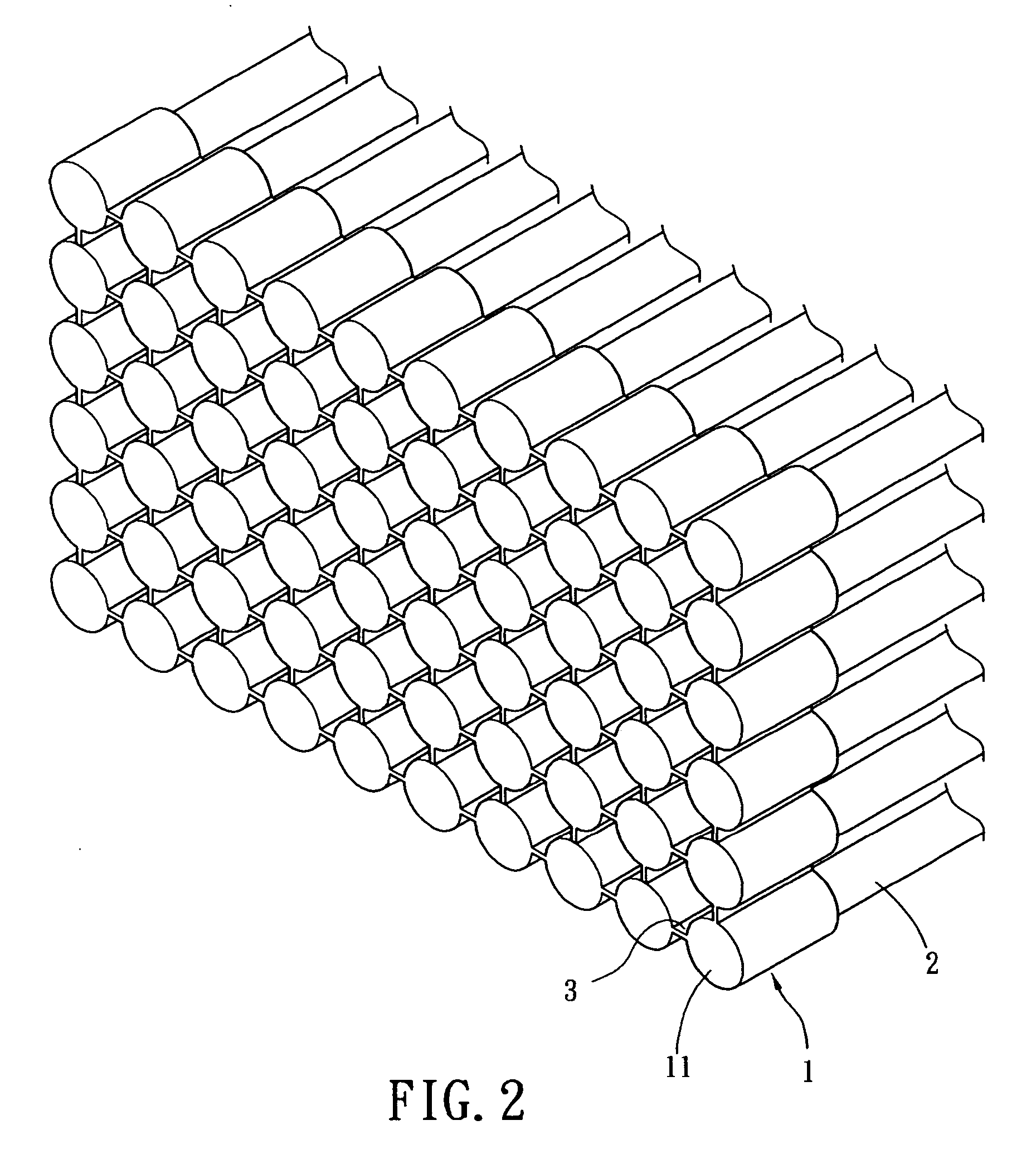
[0018]FIG. 2 shows a perspective view of the present invention. The fiber array device comprises a base 1 and a parallel optical array 2 therein. The base 1 comprises a plurality of straight bridging sections 3 to connect a plurality cylindrical containers 11 into 6×10 array arrangement. The base 1 is preferably made of material with high refractive index and light transparency such as glass. More than one cylindrical container 11 is arranged in coplanar manner. It is known to the skill in the art that the container 11 can be other shape than cylindrical shape as long as the inner diameter of the container 11 can accommodate the outer diameter of the fiber. Therefore, the fibers can be retained on the base to form 6×10 array arrangement.

[0019] As also shown in FIG. 2, the bridging sections 3 are extended symmetrically from the container 11. Therefore, the cylindrical containers 11 are connected through the rectangular bridging sections 3 therebetween. Moreover, the rectangular brid...


PUM


Abstract

An optical fiber array includes two more glass containers each with a cylindrical shape. Each container contains an optical fiber, including a convex face on outer side thereof to provide light focusing effect. Four straight bridging sections are extended symmetrically from the container and one bridging section is connected to another container to form an array-type base. Moreover, the bridging section can be an assembling and locking structure to form base with flexible shape.

Description

BACKGROUND OF THE INVENTION [0001] 1. Field of the Invention [0002] The present invention relates to an optical fiber array, especially to an optical fiber array with optical effect and flexible in shape thereof. [0003] 2. Description of Prior Art [0004] As rapid progress of communication technology, the communication speed and bandwidth are more and more demanding for electronic devices. Therefore the conventional network for data transmission such as cables are gradually replaced by medium supporting optical transmission. More particularly, parallel fiber arrays can be used for facilitating assembling of optical network. [0005] The light beam will have refraction and diffraction when the light beam leaves from the optical fiber and propagates to other medium such as air or liquid. The attenuation caused by the refraction and diffraction of the light beam is proportional to the propagation distance of the light beam. Therefore, the light will be attenuated when the light beams prop...

Claims


Application Information

Patent Timeline
IPC IPC(8): G02B6/32
CPCG02B6/322G02B6/3644G02B6/3672G02B6/3676
Inventor WENG, ALLEN
Owner WENG ALLEN
Why Eureka
Try Eureka