Method and apparatus for extracting optical clock signal

a clock signal and optical clock technology, applied in the field of optical clock signal extraction methods and apparatuses, can solve the problems of inefficiency of the method illustrated in fig. 1, difficult manufacturing of optical elements for extracting the desired clock signal, and unstable optical system, so as to reduce the influence of the pattern of input optical signals, reduce noise components, and maximize the efficiency of bi-directional amplifiers

Inactive Publication Date: 2007-04-19
ELECTRONICS & TELECOMM RES INST
View PDF8 Cites 11 Cited by
  • Summary
  • Abstract
  • Description
  • Claims
  • Application Information

AI Technical Summary

Benefits of technology

[0013] The present invention provides a method and apparatus for extracting an optical clock signal using a bi-directional amplifier and a Fabry-Perot filter, thereby greatly decreasing the influence of the pattern of an input optical signal, maximizing the efficiency of the bi-directional amplifier, and removing noise components.

Problems solved by technology

However, it is still difficult to manufacture an optical element for extracting a desired clock signal and an optical system is still unstable.
When a difference between the intensity difference and the attenuation difference is great, the method illustrated in FIG. 1 is not efficient.

Method used


Image

  • Method and apparatus for extracting optical clock signal
  • Method and apparatus for extracting optical clock signal
  • Method and apparatus for extracting optical clock signal

Examples


Embodiment Construction

[0023] Hereinafter, preferred embodiments of the present invention will be described in detail with reference to the attached drawings.

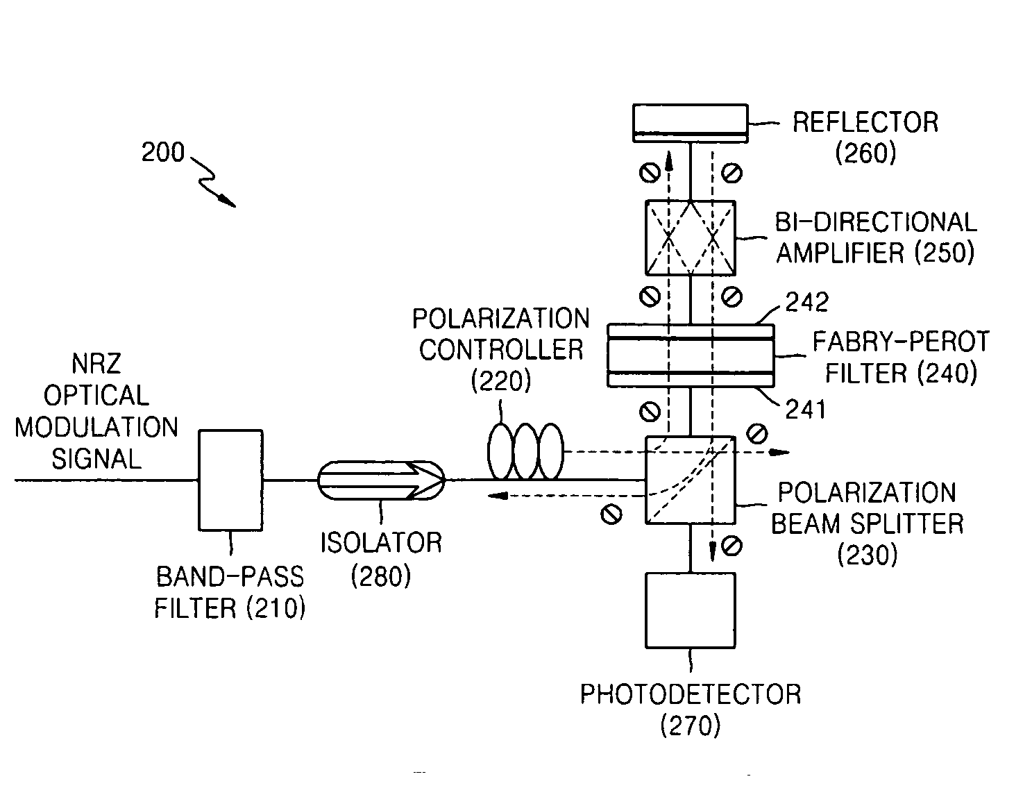
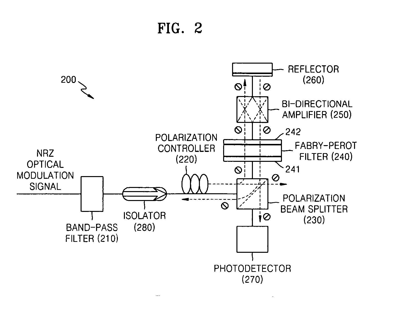
[0024]FIG. 2 is a block diagram of an apparatus 200 for extracting an optical clock signal according to an embodiment of the present invention. Referring to FIG. 2, the apparatus 200 includes a band-pass filter 210, a polarization controller 220, a polarization beam splitter 230, a Fabry-Perot filter 240, a bi-directional amplifier 250, a reflector 260, a photodetector 270, and an isolator 280. The reflector 260 may be implemented using a Faraday rotator mirror.

[0025] The band-pass filter 210 selects a predetermined frequency band with properly adjusted amplitudes in an input optical signal. The predetermined frequency band with properly adjusted amplitudes includes a central frequency component and one among a plurality of side frequency components. The input optical signal input to the band-pass filter 210 may be a non-return-to-zero (NRZ) optica...


PUM


Abstract

An apparatus and method for extracting an optical clock signal are provided. The method includes splitting a predetermined polarization component from an input optical signal, selecting frequency components for clock signal extraction from the predetermined polarization component and amplifying the selected frequency components, rotating the amplified frequency components by a predetermined angle and then reflecting them, amplifying the reflected frequency components and removing noise from the amplified frequency components using a Fabry-Perot filter, and obtaining a beat frequency component from the frequency components from which noise has been removed using the Fabry-Perot filter to extract a clock signal. Accordingly, influence of the pattern of the input optical signal is reduced and the apparatus and method are provided at low price.

Description

CROSS-REFERENCE TO RELATED PATENT APPLICATIONS [0001] This application claims the benefit of Korean Patent Application No. 10-2005-0096948, filed on Oct. 14, 2005, in the Korean Intellectual Property Office, the disclosure of which is incorporated herein in its entirety by reference.BACKGROUND OF THE INVENTION [0002] 1. Field of the Invention [0003] The present invention relates to a method and apparatus for extracting an optical clock signal, and more particularly, to a method and apparatus for extracting an optical clock signal using a bi-directional amplifier and a Fabry-Perot filter. [0004] 2. Description of the Related Art [0005] With the increase of transmission speed in optical communication and the development of transmitters converting data into optical signals, the improvement is also needed in a signal processing rate of a receiver, which receives an optical signal and converts it back to the original data. To satisfy the request, methods and apparatuses for extracting an...

Claims


Application Information

Patent Timeline
Patent Type & Authority Applications(United States)
IPC IPC(8): H04B10/00
CPCH04L7/0075H04B10/00H04B10/60
Inventor LEE, JAEMYOUNGKO, JE SOO
Owner ELECTRONICS & TELECOMM RES INST
Why Eureka
Try Eureka