Contact member, connector, substrate and contact system

a technology of contact member and substrate, applied in the direction of coupling contact member, coupling device connection, printed circuit aspect, etc., can solve the problems of increasing the number of components of the connector contact b>101/b>, complicated manufacturing procedure, etc., and achieve the effect of reducing contact failure and simplifying construction

Inactive Publication Date: 2007-04-19
FUJITSU LTD
View PDF2 Cites 9 Cited by
  • Summary
  • Abstract
  • Description
  • Claims
  • Application Information

AI Technical Summary

Benefits of technology

[0017] According to the invention, the contact failure can be reduced with a simpler construction than in the prior arts.

Problems solved by technology

Consequently, the number of components of the connector contacts 101 increases, and a manufacturing procedure becomes complicated.

Method used


Image

  • Contact member, connector, substrate and contact system
  • Contact member, connector, substrate and contact system
  • Contact member, connector, substrate and contact system

Examples


Embodiment Construction

[0028] A card edge connector 1 according to a best mode (which will hereinafter be termed an embodiment) for carrying out the invention will hereinafter be describe with reference to the drawings. A configuration in the following embodiment is an exemplification, and the invention is not limited to the configuration in the embodiment.

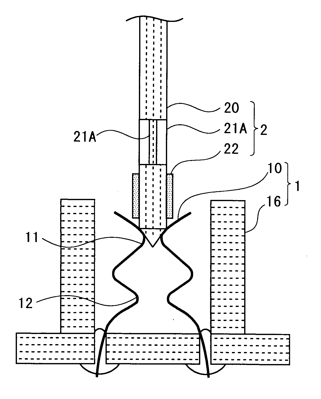
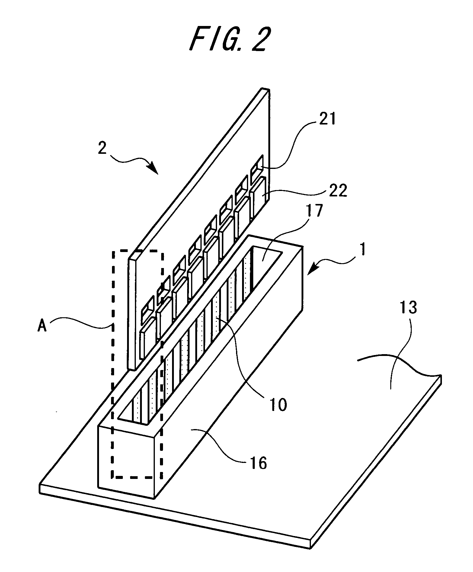
[0029]FIG. 2 is a perspective view of a substrate component (corresponding to a connector system according to the invention) including the card edge connector 1 according to one embodiment of the invention. This substrate component is constructed of a first substrate 13 (corresponding to a substrate and a first substrate according to the invention) fitted with the card edge connector 1, and a second substrate 2 (corresponding to a second substrate according to the invention) connected to the first substrate 13 by the card edge connector 1.

[0030] The first substrate 13 is, e.g., a motherboard. The card edge connector 1 is fixed by soldering etc to the ...


PUM


Abstract

A pair of contact members 10, 10 coming into contact with both of a front-surface and an undersurface of a substrate 2 by elastic forces, comprise a pair of first contact points 11, 11 getting, when the substrate 2 is inserted, apart from each other due to a thickness of the substrate 2, resisting the elastic forces, and a pair of second contact points 12, 12 coming into, when the pair of first contact points 11, 11 are biased by the elastic forces in such a direction to get close to each other within a hole 21 opened at both of the front-surface and the undersurface of the substrate 2, contact with both of the front-surface and the undersurface of the substrate 2 in a way that interlocks with the first contact points 11,11.

Description

BACKGROUND OF THE INVENTION [0001] The invention relates to a connector member, a substrate connected by the connector member and a connector system using the connector member. BACKGROUND ART [0002] There has hitherto been proposed, for instance, a card edge connector that connects, as between a motherboard and a daughterboard of a computer, a substrate and a substrate to each other (refer to, e.g., Patent document 1). [0003]FIG. 1 shows a construction of a conventional card edge connector 100. In the conventional card edge connector, there was a case in which when a substrate (daughterboard) 107 is inserted in between first contact points 102, 102 of the connector contacts 101, the connector contact 101 cuts the surface of the substrate 107, resulting in occurrence of a foreign matter (cutting chip) 108. If this foreign matter 108 is interposed between a signal terminal 109 and the connector contact 101, a failure in contact might be caused. [0004] Therefore, in the card edge conne...

Claims


Application Information

Patent Timeline
Patent Type & Authority Applications(United States)
IPC IPC(8): H01R9/22H01R13/405
CPCH01R13/26H05K1/117H05K2201/09036H05K2201/09063H05K2201/10757H05K2203/1572
Inventor MASUDA, YASUSHI
Owner FUJITSU LTD
Why Eureka
Try Eureka