System and method for visualizing conductive and current density distribution in object

a technology of conductivity and current density distribution, which is applied in the field of system and method for visualizing conductivity (or resistivity) and/or current density distribution of measuring objects, can solve the problems of poor image quality, serious drawbacks of cdi technique, and methods that cannot visualize electrical properties of human bodies or substances, etc., and achieves more accurate high resolution results

Inactive Publication Date: 2007-04-19
UNIV IND COOP GRP OF KYUNG HEE UNIV
View PDF2 Cites 18 Cited by
  • Summary
  • Abstract
  • Description
  • Claims
  • Application Information

AI Technical Summary

Benefits of technology

[0008] An object of the present invention, designed to solve the related art problem, is to provide system and method for visualization of conductivity and current density distribution, in which electrical properties (conductivity and current density) of a measuring object can be visualized in more accurate high resolution without rotating the measuring object.

Problems solved by technology

However, the methods can not visualize electrical properties of the human body or the substance.
However, the CDI has a drawback in that rotation of the measuring object in an MRI scanner is required for obtaining the magnetic flux density B having three components Bx, By, and Bz.
That is, since the component the MRI scanner can measure at a time is only the Bz component, for obtaining all the required three components of the magnetic flux density vector, the present CDI technique has a serious drawback of requiring the measuring object (the human body, or the substance) to be rotated in the MRI scanner.
However, due to a fundamental drawback of the EIT, an image of the EIT is poor, to support only a low resolution.
That is, EIT has a fundamental drawback in that a current-voltage data measured by EIT is extremely insensitive to variation of resistivity of an inside of the human body.
Therefore, clinical application of EIT is not active, presently.

Method used


Image

  • System and method for visualizing conductive and current density distribution in object
  • System and method for visualizing conductive and current density distribution in object
  • System and method for visualizing conductive and current density distribution in object

Examples


first embodiment

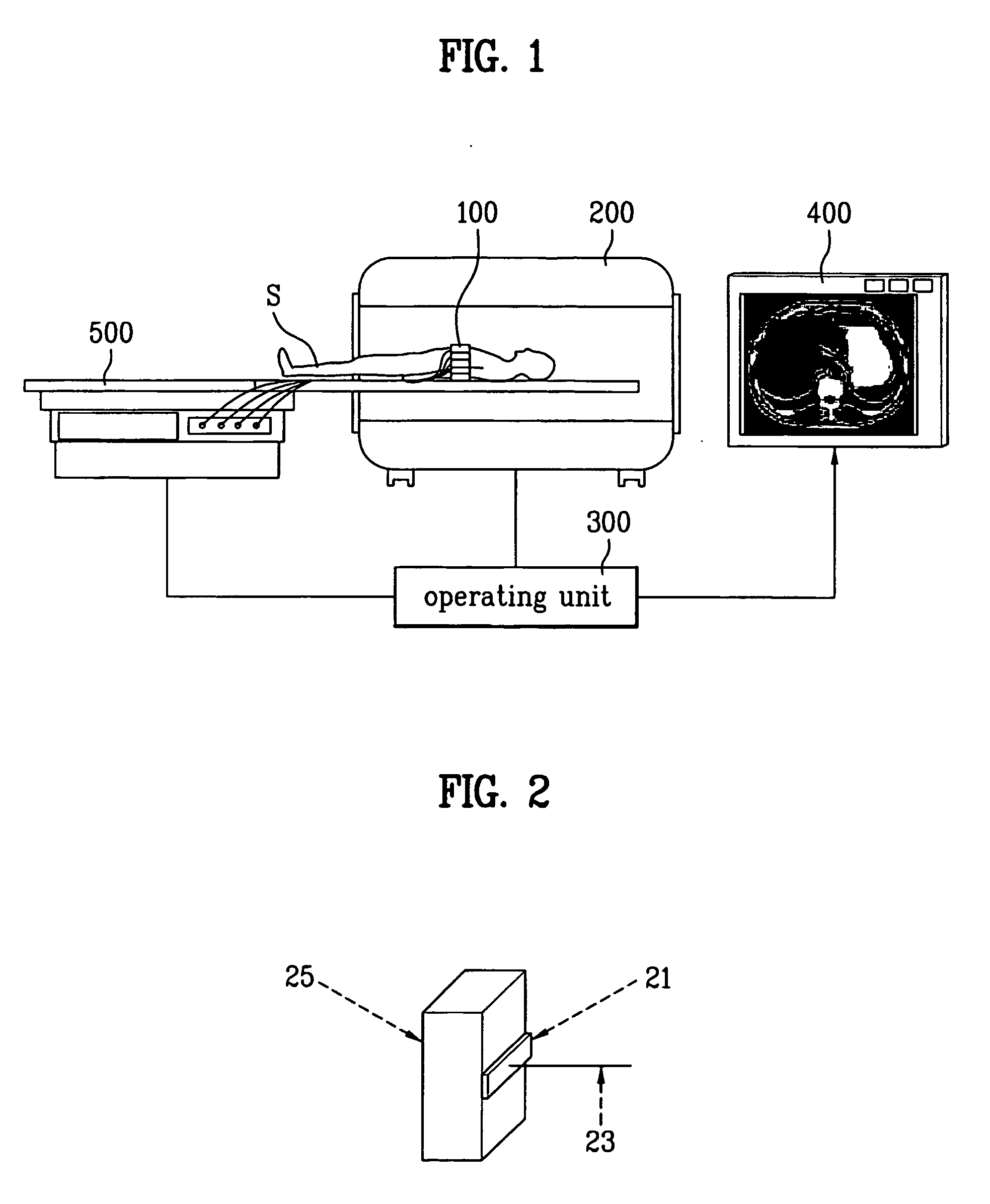
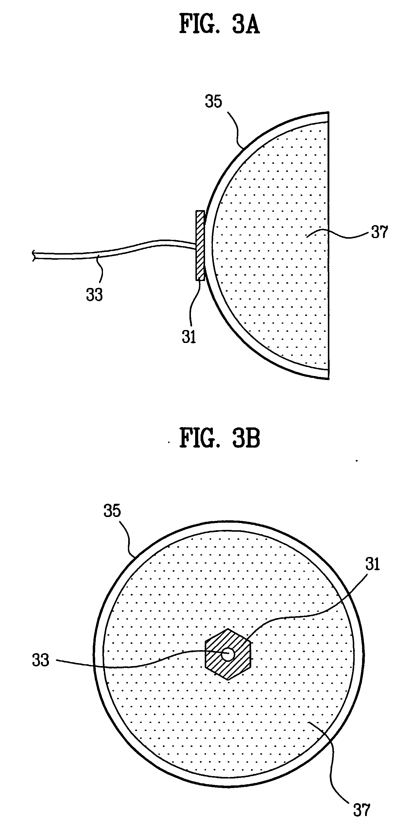
[0050] The current injecting devices 100 are attached to a circumference of a measuring object ‘S’, i.e., a human body, and injects the currents in six directions into the measuring object ‘S’ in order to induce a three-dimensional anisotropic conductivity. The currents to be injected in six directions are generated by at least the four current injecting devices. A matrix of the anisotropic conductivity A is as follows. A=[ ⁢σxxσxyσxzσyxσyyσyzσzxσzyσzz⁢ ]=[ ⁢σ11σ12σ13σ21σ22σ23σ31σ32σ33⁢ ]

[0051] The anisotropic conductivity ‘A’ has nine directional components. The anisotropic conductivity ‘A’ practically includes the six directional components because the component σ12 is identical with the component σ21, the component σ13 is identical with the component σ31, and the component σ23 is identical with the component σ32. Therefore, the current injecting devices 100 inject the currents in at least the six directions into the measuring object ‘S’ in order to induce the anisotropic conduct...

second embodiment

[0073] The current is injected into the measuring object ‘S’ in two directions or more in succession in order to induce a conductivity σ, and is generated by at least 3 current injecting devices 100.

[0074] The measuring object ‘S’ is placed in the MRI scanner 200, and the pairs of the current injecting devices 100 are selected one by one in succession, and the current Ij (j=1, 2, . . . , N) is supplied to an inside of the measuring object ‘S’ through the pair of the current injecting devices 100 selected in succession. The MRI scanner 200 measures the magnetic flux densities B1z, B2z, . . . BNz due to the currents I1, I2, . . . IN injected into the measuring object ‘S’ respectively, the non-selected current injecting devices 100 measure a surface voltage Vj|∂S of the measuring object ‘S’ when the selected pair of the current injecting devices 100 injects the current into the measuring object ‘S’.

[0075] Then, the operating unit 300 applies the magnetic flux densities B1z B2z, . . ....

third embodiment

[0106] The measuring object ‘S’ is placed in the MRI scanner 200, and the pairs of the current injecting devices 100 are selected one by one in succession, and the current Ij (j=1, 2, . . . , N) is supplied to an inside of the measuring object ‘S’ through the pair of the current injecting devices 100 selected in succession. The MRI scanner 200 measures the magnetic flux densities B1z, B2z, . . . BNz due to the currents I1, I2, . . . , IN injected into the measuring object ‘S’ respectively, the non-selected current injecting devices 100 measure a surface voltage Vj|∂S of the measuring object ‘S’ when the selected pair of the current injecting devices 100 injects the current into the measuring object ‘S’.

[0107]FIG. 6A illustrates an ideal image of the magnetic flux density not including the noises, FIG. 6B illustrates an image of the magnetic flux density including the noises. Referring to FIG. 6B, the measured magnetic flux density Bjz includes the noises due to the mechanical error...


PUM

PropertyMeasurementUnit
conductivityaaaaaaaaaa
current densityaaaaaaaaaa
magnetic flux densityaaaaaaaaaa

Abstract

System for visualizing conductivity and current density distributions including a plurality of current injecting devices (100) for injecting currents into a measuring object; a measuring unit (200) for measuring a magnetic flux density due to the currents injected into a measuring object; an operating unit (300) for selecting one pair of the current injecting devices in succession so as to inject currents of different directions into the measuring object, and calculating directional components of an anisotropic conductivity inside of the measuring object on the basis of the measured magnetic flux density; and displaying means for visualizing an inside of the measuring object by using the calculated directional components of the anisotropic conductivity.

Description

TECHNICAL FIELD [0001] The present invention relates to system and method for visualization of conductivity (or resistivity) and / or current density distributions of a measuring object, such as a human body, or a substance. BACKGROUND ART [0002] In general, X-ray, MRI, or ultrasound is used in visualization of an inside structure of the human body or the substance. However, the methods can not visualize electrical properties of the human body or the substance. [0003] As an effort for solving the problem, a method for visualizing current density distribution of an inside of a measuring object using the MRI is initially suggested by a research team of the Toronto University in 1989, and, thereafter, there have been active researches related thereto. This is the Current Density Imaging (CDI) technique. In the present CDI, a magnetic flux density B due to an injected current I is measured by using MRI technique, and a current density J is calculated by using the Ampere's law J=1 / μ0∇×B, f...

Claims


Application Information

Patent Timeline
Patent Type & Authority Applications(United States)
IPC IPC(8): A61B5/05A61BA61B5/053A61B5/055G01N27/72
CPCA61B5/0536A61B5/055A61B5/4504G01N27/72G01R33/4808
Inventor WOO, EUNG JESEO, JIN KEUNKWON, OH INKIM, TAE SEONGLEE, BYUNG ILLEE, SUK HO
Owner UNIV IND COOP GRP OF KYUNG HEE UNIV
Why Eureka
Try Eureka