
Medical instrument and medical equipment for treatment, and rotational handle device

a technology of medical instruments and handle devices, applied in the field of rotational handle devices, can solve the problems of delayed transmission of rotation upon applying torque to the handle device of the tube-shaped medical instrument at the distal end, and the inability to easily penetrate the total occlusion, etc., to prevent excessive torque

Inactive Publication Date: 2007-04-19
FMD
View PDF6 Cites 157 Cited by
  • Summary
  • Abstract
  • Description
  • Claims
  • Application Information

AI Technical Summary

Benefits of technology

[0010] In view of the foregoing problems, an object of the present invention is to provide a medical instrument and medical equipment for treatment, and a rotational handle device, in which rotation can be transmitted to a distal end or tubular tip by preventing application of excessive torque.
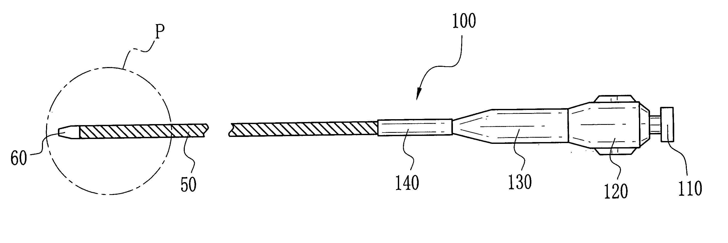
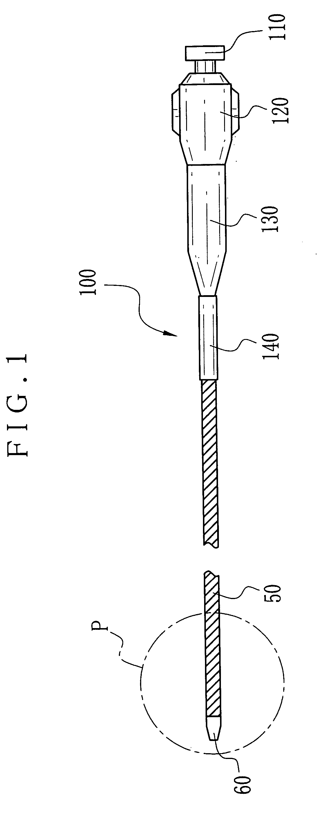
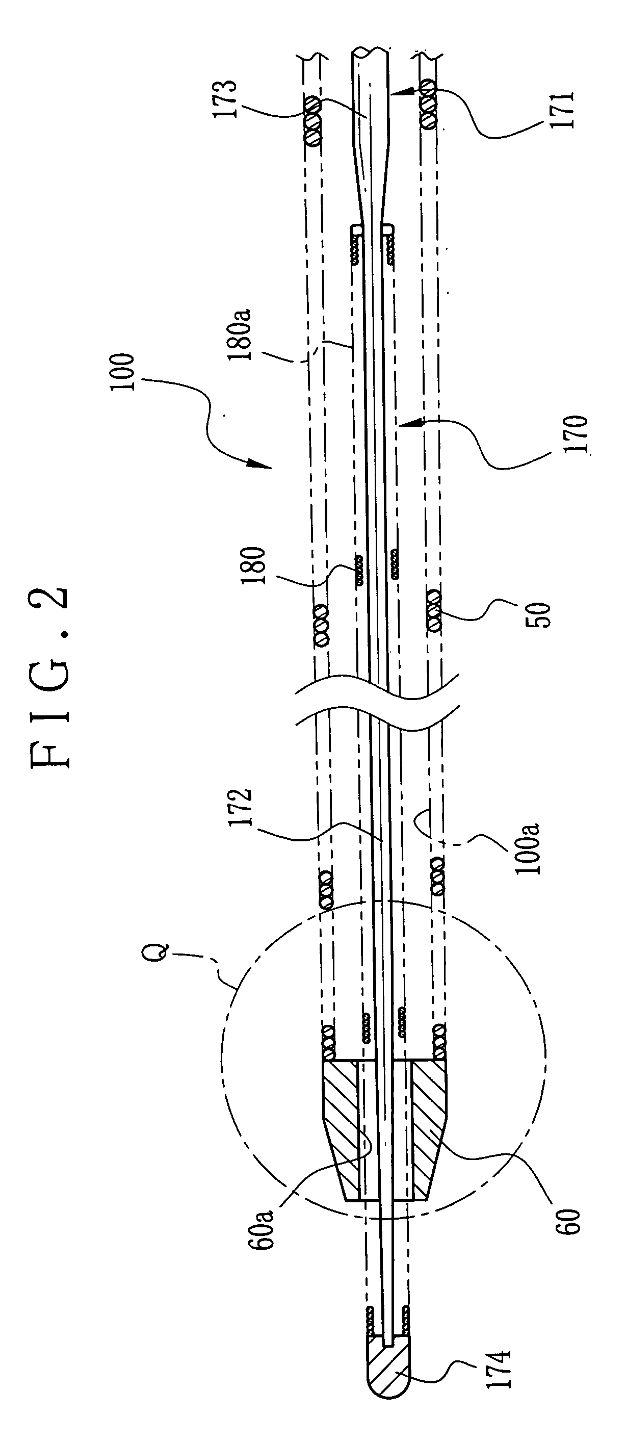
[0023] Also, a rotational handle device rotates a medical instrument for treatment in a tubular form including a tube for insertion by guiding of a medical guide wire inside. The tube includes a helical coil of metal, a tubular tip of metal secured to an end of the helical coil, and a cutting head of a blade shape, formed on the tubular tip, for cutting a lesion upon being rotated. A first rotatable tube rotates with the tube, the first rotatable tube having a wire lumen for receiving insertion of the medical guide wire. An externally operable second rotatable tube is secured to the first rotatable tube in an axial direction. An over torque preventing mechanism is disposed between the first and second rotatable tubes, for transmitting rotation of the second rotatable tube to the first rotatable tube upon application of torque equal to or lower than a predetermined level to the second rotatable tube, and for causing the second rotatable tube to rotate free from the first rotatable tube upon application of torque higher than the predetermined level to the second rotatable tube.

Problems solved by technology

A difficulty lies in that the total occlusion cannot be penetrated readily.
This problem is serious in particular if calcified content with high hardness is contained in a position short of the second end.
There is a problem in a lag of rotation, namely in that transmission of rotation upon applying torque to a handle device of the tube shaped medical instrument is delayed at the distal end.
It is likely accidentally to transmit excessive torque to the distal end, to cause perforation of the blood vessel or other false treatment as failure of the tube shaped medical instrument.
The tubular tip is captured and rotates freely to cause failure in the advance.

Method used


Image

  • Medical instrument and medical equipment for treatment, and rotational handle device
  • Medical instrument and medical equipment for treatment, and rotational handle device
  • Medical instrument and medical equipment for treatment, and rotational handle device

Examples


example 1

[0094] In FIGS. 3A-3D, cutting heads or blades of tubular tips of Example 1 are illustrated, the structures including a first structure of FIG. 3A, a second structure of FIG. 3B, a third structure of FIG. 3C, and a fourth structure of FIG. 3D. The tubular tip 60 has the cutting head 10 with a surface to extend toward the axis. A tubular tip 61 has a cutting head or blade 11. Also, tubular tips 62 and 63 have cutting heads or blades 12 and 13. In FIG. 3A, the first structure has the cutting head 10 constituted by two V shaped notches positioned opposite to one another relative to the center. In FIG. 3B, the second structure has the cutting head 11 constituted by four V shaped notches positioned regularly at four points defined by equally dividing the circumference. In FIG. 3C, the third structure has the cutting head 12 constituted by inclined V shaped notches formed at two points at the end of the tubular tip 62. In FIG. 3D, the fourth structure has the cutting head 13 constituted o...

example 2

[0099] In FIGS. 8A-8D, cutting heads or blades of tubular tips of Example 2 are illustrated in a perspective view, the structures including a first structure of FIG. 8A, a second structure of FIG. 8B, a third structure of FIG. 8C, and a fourth structure of FIG. 8D. Cutting heads or blades 20, 21, 22 and 23 are inclined cutting edges relative to an axial direction. In FIG. 8A, a first structure is illustrated. The cutting head 20 has a cutting edge 20a, which extends along a straight line contained in one plane passing the axis and at one point on an end face 70a of a tubular tip 70. A cutting edge 20b is inclined relative to the axial direction and opposed to the cutting edge 20a.

[0100] In FIG. 8B, a second structure is illustrated. The cutting head or blade 21 has an end inclined cutting edge 21c, which is defined by recessing the cutting edge 20b of the cutting head 20 in FIG. 8A. A tubular tip 71 has an end face 71a. A cutting edge 21a lies at a point on the end face 71a and ext...

example 3

[0104] In FIGS. 9A-9H, cutting heads or blades of tubular tips of Example 3 are illustrated in a side elevation and front elevation, the structures including a first structure of FIGS. 9A and 9B, a second structure of FIGS. 9C and 9D, a third structure of FIGS. 9E and 9F, and a fourth structure of FIGS. 9G and 9H. In FIGS. 9A and 9B, a tubular tip 80 has a cutting head or blade 30. Notch formed cutting edges 30a and 30b are disposed on the cutting head 30, and are symmetrical with one another with reference to a centerline passing the center of the tubular tip 80. In FIGS. 9C and 9D, a tubular tip 81 has a cutting head or blade 31. Notch formed cutting edges 31a and 31b are disposed on the cutting head 31, and are asymmetrical with one another with reference to a centerline passing the center of the tubular tip 81. In FIGS. 9E and 9F, a tubular tip 82 has a cutting head or blade 32. Crescent shaped cutting edges 32a and 32b are disposed on the cutting head 32, and are symmetrical wi...


PUM


Abstract

A rotational handle device rotates a medical instrument for vascular treatment in a tubular form including a tube for insertion by guiding of a medical guide wire inside. The tube includes a helical coil of metal, a tubular tip of metal secured to an end of the helical coil, and a cutting head of a blade shape, formed on the tubular tip, for cutting a lesion upon being rotated. A first rotatable tube rotates with the tube, and has a wire lumen. An externally operable second rotatable tube is secured to the first rotatable tube in an axial direction. An over torque preventing mechanism is disposed between the first and second rotatable tubes, and causes the second rotatable tube to rotate free from the first rotatable tube upon application of torque higher than the predetermined level to the second rotatable tube.

Description

BACKGROUND OF THE INVENTION [0001] 1. Field of the Invention [0002] The present invention relates to a medical instrument and medical equipment for treatment, and a rotational handle device. More particularly, the present invention relates to a medical instrument and medical equipment for treatment, and a rotational handle device, in which rotation can be transmitted to a distal end or tubular tip by preventing application of excessive torque. [0003] 2. Description Related to the Prior Art [0004] A catheter is a tube shaped rotational medical instrument by insertion in a blood vessel of a patient. For use of the catheter, at first a guide wire is inserted the blood vessel before the catheter in a tubular shape is inserted by following the wire surface of the guide wire. The guide wire inserted in the blood vessel is used for inserting the catheter for injecting X-ray contrast agent, or for inserting a balloon catheter or stent for deployment against a constriction. Any of the guide ...

Claims


Application Information

Patent Timeline
Patent Type & Authority Applications(United States)
IPC IPC(8): A61M25/00
CPCA61B17/3207A61B17/320758A61B2017/22044A61B2017/22094A61B2017/320032A61B2019/301A61M25/0043A61M25/0069A61M25/0097A61M25/09A61M2025/09083A61M2025/09125A61B2090/031
Inventor TERASHI, TSUYOSHISHIMURA, SEIJI
Owner FMD
Learn More