
Technique for timeline compression in a data store

a timeline and data storage technology, applied in the field of data storage, can solve the problems of limited data recovery capabilities, simple storage increase may not scale well, and significant amount of storage space is needed, and achieve the effect of reducing the granularity level of the timelin

Active Publication Date: 2007-04-19
SYMANTEC OPERATING CORP
View PDF99 Cites 31 Cited by
  • Summary
  • Abstract
  • Description
  • Claims
  • Application Information

AI Technical Summary

Benefits of technology

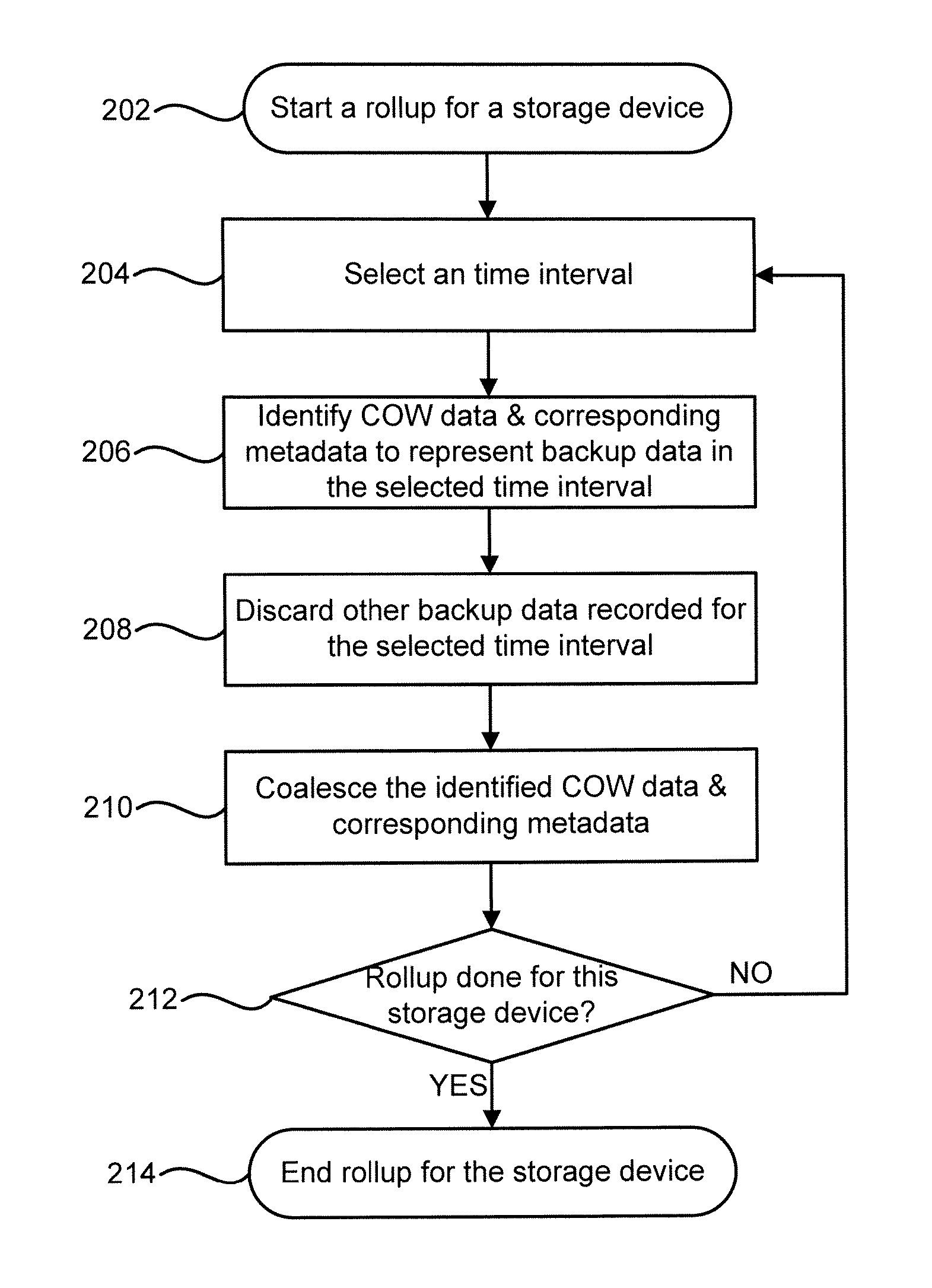
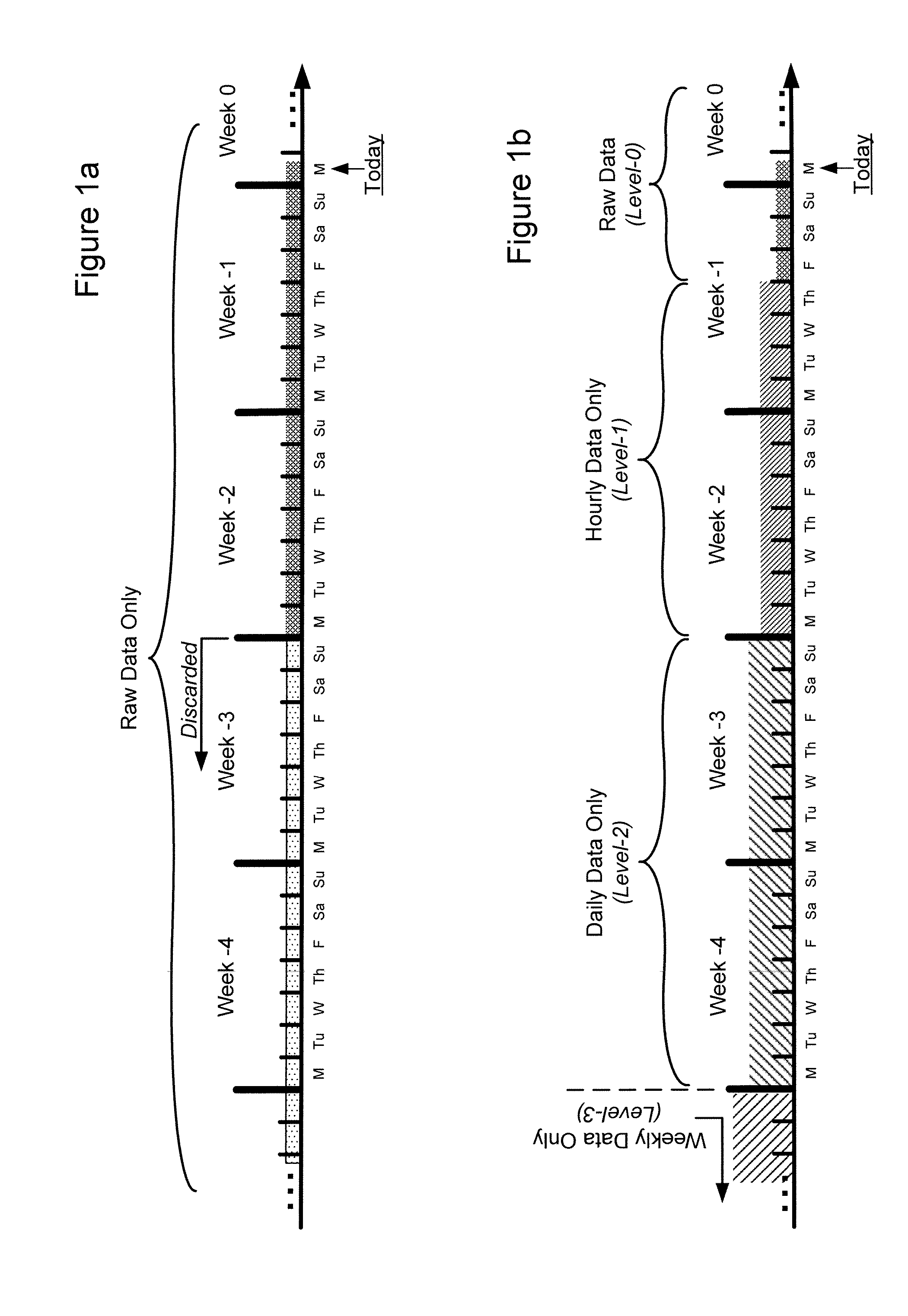
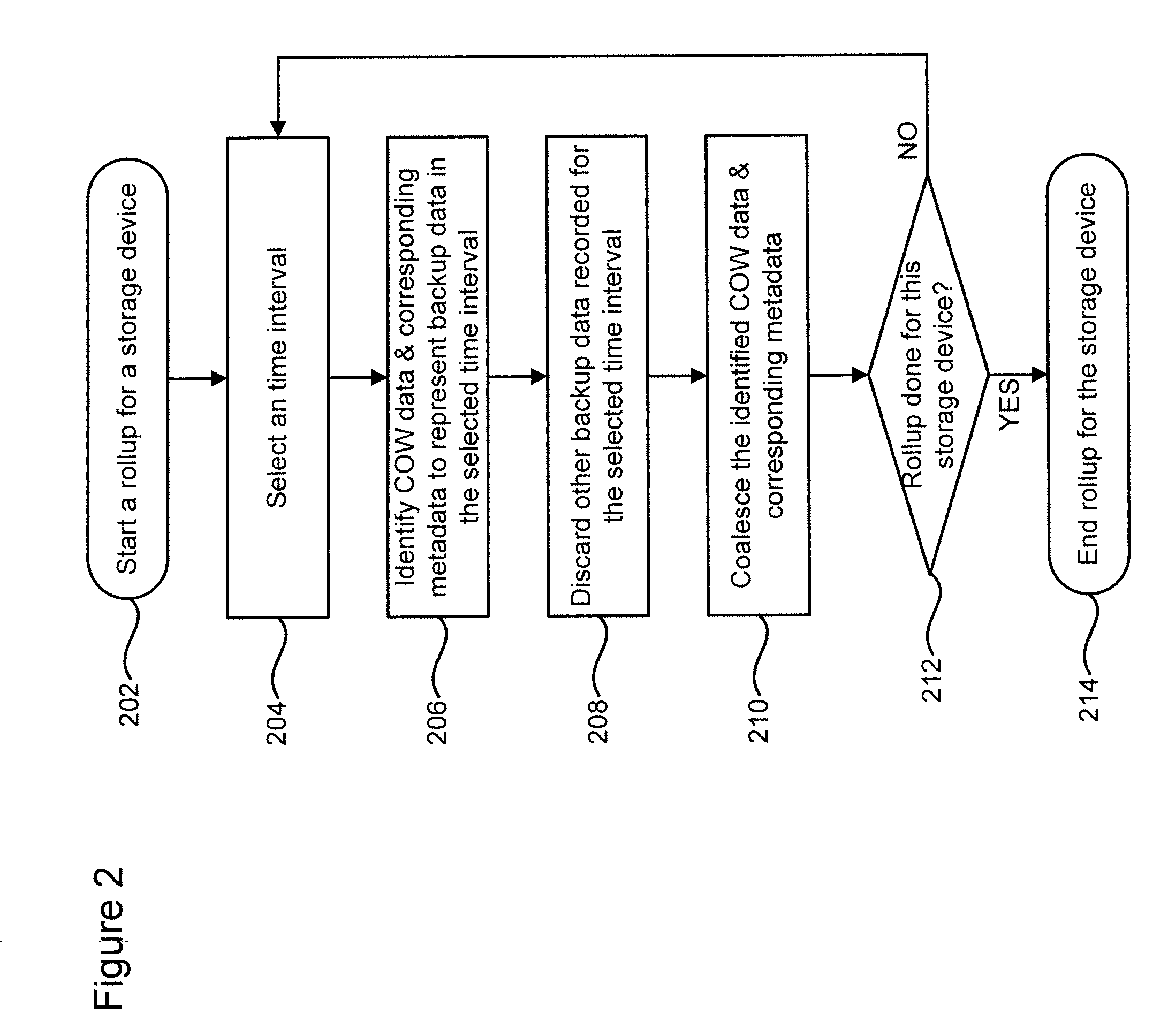
[0008] A technique for timeline compression in a data store is disclosed. In one particular exemplary embodiment, the technique may be realized as a method for timeline compression in a storage system, wherein digital content of the storage system is backed up to enable restoration of the digital content to one or more points in a timeline. The method may comprise selecting a time interval in the timeline. The method may also comprise identifying one or more sets of backup data recorded for the selected time interval, wherein the identified one or more sets of backup data represent at least a portion of old data overwritten during the selected time interval. The method may further comprise discarding other backup data recorded for the selected time interval, thereby reducing a granularity level of the timeline in the selected time interval.
[0018] In accordance with another aspect of this particular exemplary embodiment, the method may further comprise scanning the storage system for a storage device for which the granularity of the timeline can be reduced.
[0021] In still another particular exemplary embodiment, the techniques may be realized as a system for timeline compression in a storage system, wherein digital content of the storage system is backed up to enable restoration of the digital content to one or more points in a timeline. The system may comprise means for selecting a time interval in the timeline. The system may also comprise means for identifying one or more sets of backup data recorded for the selected time interval, wherein the identified one or more sets of backup data represent at least a portion of old data overwritten during the selected time interval. The system may further comprise means for discarding other backup data recorded for the selected time interval, thereby reducing a granularity level of the timeline in the selected time interval.
[0022] In a further particular exemplary embodiment, the techniques may be realized as a system for timeline compression in a storage system, wherein digital content of the storage system is backed up to enable restoration of the digital content to one or more points in a timeline. The system may comprise a storage medium for storing instructions. The system may also comprise at least one processor for: selecting a time interval in the timeline; identifying one or more sets of backup data recorded for the selected time interval, wherein the identified one or more sets of backup data represent at least a portion of old data overwritten during the selected time interval; and discarding other backup data recorded for the selected time interval, thereby reducing a granularity level of the timeline in the selected time interval.

Problems solved by technology

However, to accommodate an extended timeline, a significant amount of storage space is needed to store the COW data and corresponding metadata for every write command in that timeline.
However, apart from a higher cost, a simple storage increase may not scale well with the rest of the system and tends to create a deluge of other problems, such as a performance degradation due to difficulties of parsing through an additional amount of data.
In these systems, data recovery capabilities are limited to the past few days for which backup data are available.
Such a brute-force solution can be costly and disruptive, not to mention its slow response to data recovery requests where off-site data are needed.

Method used


Image

  • Technique for timeline compression in a data store
  • Technique for timeline compression in a data store
  • Technique for timeline compression in a data store

Examples


Embodiment Construction

[0032] As used herein, “backup data” refers generally to data that have been recorded and / or organized (or even re-organized) with a purpose of restoring or recovering digital content of a storage system.

[0033]“Copy-on-write data” (or “COW data”) refers to substantive data (e.g., new data to be written or old data to be overwritten in response to a write command) that have been recorded in a copy-on-write operation. New data to be written in response to a write command are sometimes referred to as “after image data” or “after image,” while old data to be overwritten in response to a write command are sometimes referred to as “before image data” or “before image.” The copy-on-write operation may be an actual operation performed in response to an actual write command. Or, the copy-on-write operation may be a virtual operation that includes the collective effect of multiple copy-on-write operations that occur during a selected time interval.

[0034]“Corresponding metadata” refers to in...


PUM


Abstract

A technique for timeline compression in a data store is disclosed. In one particular exemplary embodiment, the technique may be realized as a method for timeline compression in a storage system, wherein digital content of the storage system is backed up to enable restoration of the digital content to one or more points in a timeline. The method may comprise selecting a time interval in the timeline. The method may also comprise identifying one or more sets of backup data recorded for the selected time interval, wherein the identified one or more sets of backup data represent at least a portion of old data overwritten during the selected time interval. The method may further comprise discarding other backup data recorded for the selected time interval, thereby reducing a granularity level of the timeline in the selected time interval.

Description

CROSS-REFERENCE TO RELATED APPLICATIONS [0001] This patent application claims priority to U.S. Provisional Patent Application No. 60 / 726,187, filed Oct. 14, 2005, which is hereby incorporated by reference herein in its entirety. [0002] This patent application is related to U.S. patent application Ser. No. 10 / 924,652, filed Aug. 24, 2004, which is a continuation-in-part of U.S. patent application Ser. No. 10 / 668,833, filed Sep. 23, 2003, each of which is hereby incorporated by reference herein in its entirety.FIELD OF THE DISCLOSURE [0003] The present disclosure relates generally to data storage and, more particularly, to a technique for timeline compression in a data store. BACKGROUND OF THE DISCLOSURE [0004] In related U.S. patent application Ser. No. 10 / 924,652 and U.S. patent application Ser. No. 10 / 668,833, a time-dependent data storage and recovery technique is disclosed. Embodiments of such a technique provide a solution for continuous data protection (CDP) wherein write comma...

Claims


Application Information

Patent Timeline
IPC IPC(8): G06F11/00G06F12/16
CPCG06F11/1435G06F11/1451G06F11/1458G06F17/30943G06F2201/835G06F2201/84G11B27/105G06F11/1461G06F16/90
Inventor PASSERINI, RONALD PETERPERRY, ROBERT WARRENROCCA, CHRISTOPHER ANGELOANTHONY, MICHAEL DANIEL
Owner SYMANTEC OPERATING CORP
Learn More