Energy efficient air handling system for cleanrooms

a technology for air handling systems and cleanrooms, applied in lighting and heating apparatus, heating types, instruments, etc., can solve the problems of inefficiency and unnecessarily high energy consumption, no process has been able to optimize energy savings, and the air leaving the cooling coil would be too cold for the cleanroom environment. , to achieve the effect of reducing installation and operating costs

Inactive Publication Date: 2007-04-26
JAISINGHANI RAJAN A
View PDF4 Cites 15 Cited by
  • Summary
  • Abstract
  • Description
  • Claims
  • Application Information

AI Technical Summary

Benefits of technology

[0006] It is there, one object of the present invention to provide a more efficient refrigeration based air handling system exhibiting lower installation and operating costs.
[0008] It is still another object to provide an air handling process and system endowed with an ability to minimize, or to eliminate, the use of energy to reheat the air.
[0010] It is still yet another object to minimize or even eliminate reheating of the air flow from an air handling unit.
[0012] These and other objects may be achieved with a refrigeration based air handling system design process for significant energy and cost savings in clean room and other environmentally controlled applications of enclosed volumes requiring large air change rates. The process utilizes an air flow by pass around the air conditioning system, with the ratio of bypassed air flow to air conditioned flow being established to necessitate minimal or no reheat of the combined bypassed and conditioned air flow required for applications having relative humidity control requirements, and with relative humidity control being achieved via cooling.
[0013] When dehumidification is achieved by adsorptive processes, the bypass ratio is varied so as to minimize cooling of the heated dry air. In other non-relative humidity control applications the bypass is varied to minimize the air conditioning flow, thereby decreasing cost, but with optimum cooling coil velocities in a manner that minimizes consumption of energy necessary to maintain airflow through the system.

Problems solved by technology

Typically, this means that the air leaving the cooling coil would be too cold for the cleanroom environment; in other words, in such a dehumidification system the air has been cooled to a temperature that is in excess of the sensible heat load of the environmentally controlled space; therefore the air leaving the cooling coil must be re-heated to the required temperature.
I have found that both the cooling of the air to a dew point corresponding to the required moisture content level followed by reheating in dehumidification processes, as well as the heating of the air to achieve adsorption followed by cooling of the air in an adsorption process, are inefficient and unnecessarily expensive in terms of the energy consumed.
Although a by pass of airflow may occur around the air conditioning unit of an air handling unit in these processes, the by pass is incidental and no process has been able to optimize energy savings and minimize or eliminate reheating by harnessing a by pass of air flow during the air handling process.

Method used


Image

  • Energy efficient air handling system for cleanrooms
  • Energy efficient air handling system for cleanrooms
  • Energy efficient air handling system for cleanrooms

Examples


Embodiment Construction

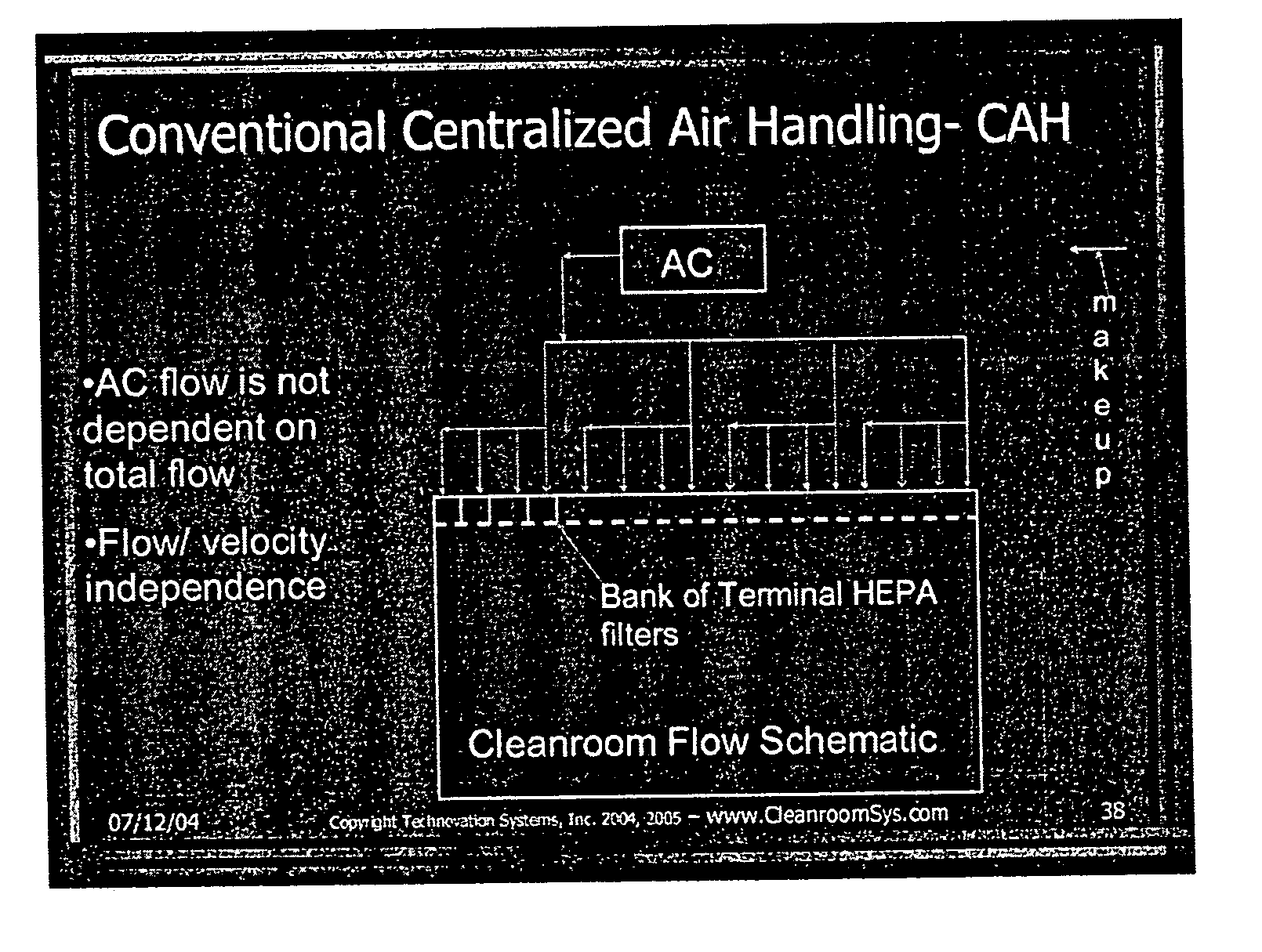
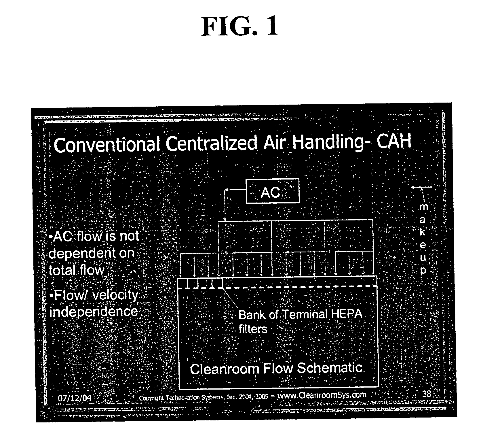
[0034] Turning now to the drawings, FIG. 1 illustrates an airflow schematic in a system that relies upon dehumidification by means of cooling; the most common air handling system used in cleanrooms is the central air handling (CAH) system—in this case the entire return airflow is circulated through a central air handler. In this system the return air, known as the re-circulated air, is mixed with the make up air which is drawn either from the outer environment or from a first stage make up air conditioning unit. The combined return air and make up air is then conditioned for both moisture content (relative humidity (i.e., also known as “RH”)) and temperature. In central air handling systems, the supply air must be at a temperature suitable to meet the sensible heat load of the clean room (i.e., the clean room is an environmentally controlled space). The air is cooled to a dew point corresponding to the required moisture content level, and the excess moisture condensed on the cooling...


PUM


Abstract

A refrigeration based air handling system design process for significant energy and cost savings in cleanroom and other applications requiring large air change rates is presented. The process utilizes a by pass around the air conditioning system, the ratio of bypass to air conditioning flow being such that minimal or no reheat of the air is required for applications having relative humidity (RH) control requirements and with RH control being achieved via cooling. If dehumidification is achieved by adsorptive processes, then the by pass ratio is varied so as to minimize cooling of the heated dry air. In other non relative humidity control applications the bypass is varied to minimize the air conditioning flow, thereby decreasing cost, but by using optimum cooling coil velocities in a manner such that system energy for airflow is minimized. The energy and cost savings achieved by this process vary between 65% to 15% depending on the Class of the cleanroom and / or on the number of air changes per hour required.

Description

BACKGROUND OF THE INVENTION [0001] 1 Technical Field [0002] This application pertains to heating, ventilating and air conditioning systems and processes generally, and, more particularly, to energy efficiency in heating, ventilating and air conditioning systems and air handling processes for clean rooms and other environmentally controlled spaces that require large air change rates. [0003] 2 Description of Related Art [0004] In air handling systems applicable to cleanrooms and other applications requiring large air exchange rates, the air is cooled to meet the sensible heat load of the cleanroom. If the cleanroom or other enclosed environment is to have relative humidity (RH) control in addition to a large air exchange rate, and if dehumidification is achieved by cooling, then the air is cooled to a dew point corresponding to the required moisture content level by allowing the excess moisture to condense on the cooling coils of the air conditioning system. Typically, this means that...

Claims


Application Information

Patent Timeline
Patent Type & Authority Applications(United States)
IPC IPC(8): A23C3/02
CPCF24F3/0442F24F3/161F24F3/167
Inventor JAISINGHANI, RAJAN A.
Owner JAISINGHANI RAJAN A
Why Eureka
Try Eureka