Fluid filter element

Inactive Publication Date: 2007-04-26
MANN HUMMEL GMBH
View PDF12 Cites 10 Cited by
  • Summary
  • Abstract
  • Description
  • Claims
  • Application Information

AI Technical Summary

Benefits of technology

[0004] It is therefore an object of the invention to provide an improved fluid

Problems solved by technology

However, an eccentrically positioned inlet opening poses problems when connecting the filter element.
However, the increased structural height of

Method used


Image

  • Fluid filter element
  • Fluid filter element
  • Fluid filter element

Examples


Embodiment Construction

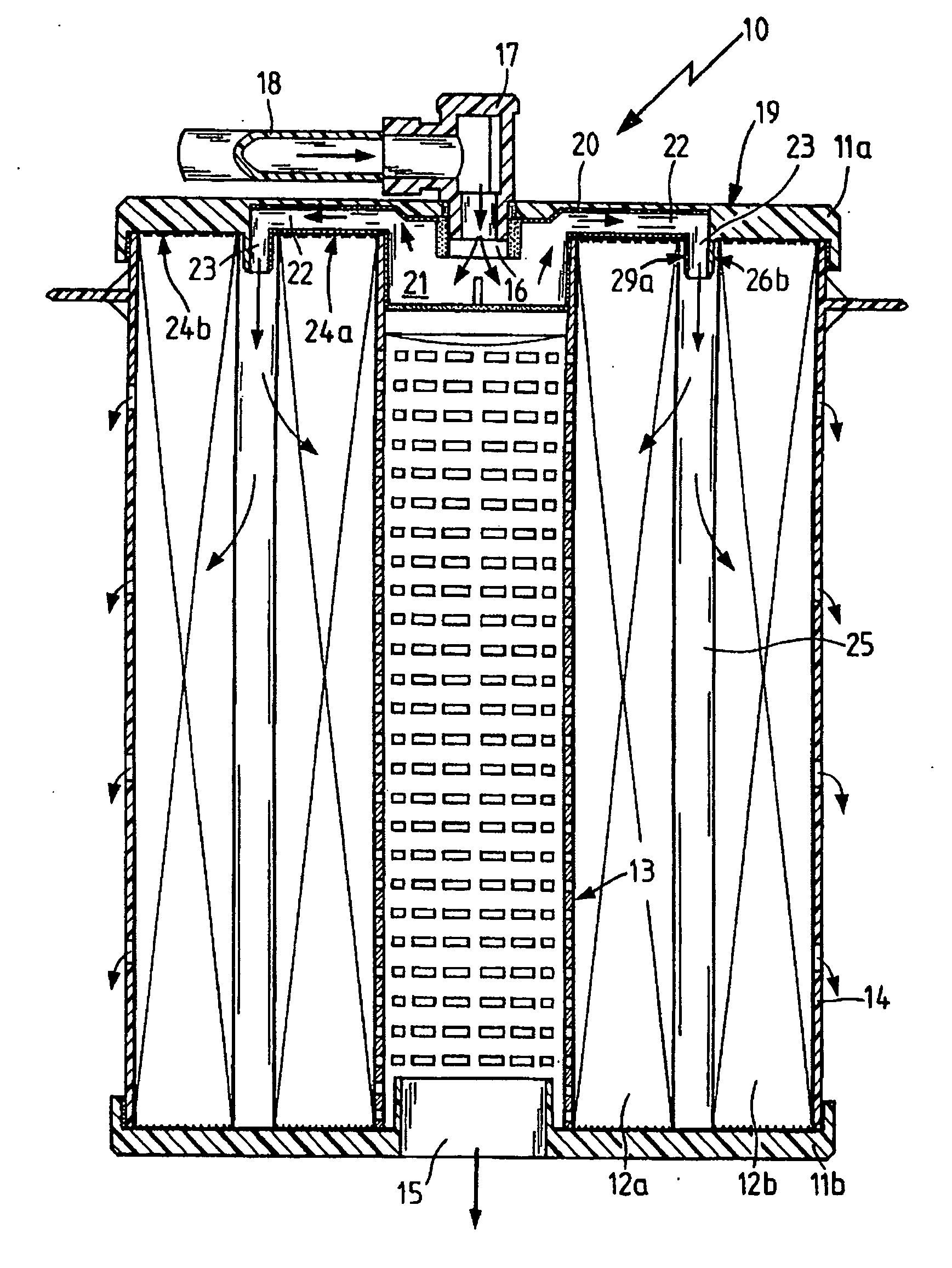
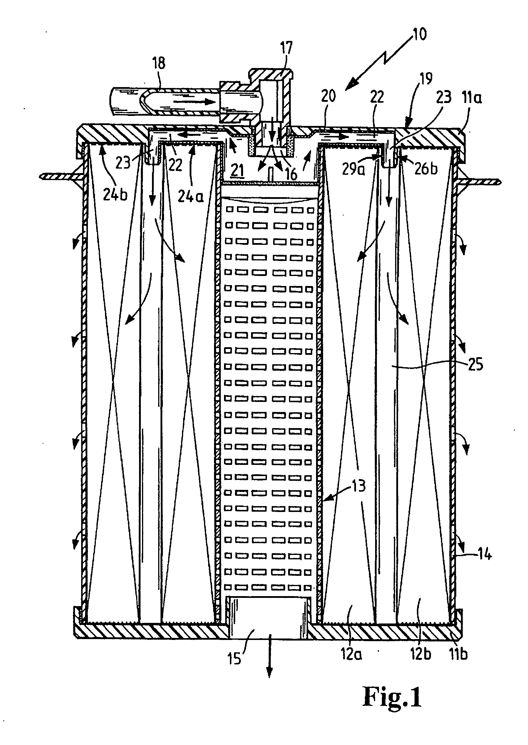
[0028]FIG. 1 shows a filter element 10 for fluids, in particular coolant, lubricant or machining liquids from machine tools. The filter element comprises an upper end disk 11a and a lower end disk 11b between which an inner ring of filter material 12a and an outer ring of filter material 12b are arranged in a sealed manner. The rings of filter material 12a and 12b have a closed hollow cylindrical construction, and preferably comprise a pleated or zig-zag folded filter medium.

[0029] An inner supporting tube 13 is situated inside of the inner ring of filter material 12a, and an outer supporting tube 14 is arranged as a jacket around the outer ring of filter material 12b. The support tubes 13 and 14 are preferably made of a synthetic resin material by an injection molding process or an extrusion process and are fluid-permeable. The support tubes 13 and 14 are preferably non-detachably joined to the end disks 11a, 11b by a bonding or welding method.

[0030] The lower end disk 11b has a ...


PUM

PropertyMeasurementUnit
Pressureaaaaaaaaaa
Heightaaaaaaaaaa
Permeabilityaaaaaaaaaa

Abstract

A compact filter element with a large filter surface area having inner and outer rings of filter material with an annular space between them, such that fluid to be filtered can be introduced into the annular space between the rings of filter material and a portion thereof can flow through the outer ring of filter material to the periphery of the filter element and another portion thereof can flow through the inner ring of filter material to the center of the filter element; at least one fluid-permeable support member for the filter material, and at least one end disk on an axial end face of the filter element affixed to the rings of filter material in a sealed manner, in which the end disk has a centrally arranged inlet opening for the fluid to be filtered and one or more radially extending distributor channels leading from the central inlet opening to at least one eccentrically arranged outlet opening which opens into the annular space between the rings of filter material to admit fluid to be filtered to the annular space.

Description

BACKGROUND OF THE INVENTION [0001] The present invention relates to a filter element for fluids which provides a large filter surface area in a compact volume. [0002] Published German patent application no. DE 196 08 589 discloses a filter element for gaseous or liquid media which can be inserted into a filter housing. The filter element has a filter medium that is pleated in a zigzag pattern and closed to form a ring. End disks are arranged on the ends of the filter medium. Fluid flows through the filter element from the inside to the outside, so the particles of dirt striking the filter element form a filter cake on the surface of the filter element. This is understood to improve the filter fineness of the filter medium. In certain use situations, such filters may also be used without a housing, so an outer supporting jacket is needed for such an application. In the state of the art, this is accomplished by a perforated outer jacket. The outer jacket is made either of perforated s...

Claims


Application Information

Patent Timeline
IPC IPC(8): B24B57/00B01D29/00
CPCB01D29/21B01D29/232B01D29/54B01D2201/298
Inventor BAUDER, RALFWOLF, MICHAELMUENKEL, KARLHEINZSTINZENDOERFER, JOACHIMNGUYEN, DUC CUONGSCHERER, OLIVERGRUBER, MARTIN
Owner MANN HUMMEL GMBH
Why Eureka
Try Eureka