[0011] The present invention provides an improved
magnetic filter device configured to separate contaminant material from a fluid without the disadvantages associated with known filters. The
magnetic core of the filter device of the present invention comprises at least four columns of magnets, each column having a single, substantially uniform polarity extending along its length. The magnets are positioned lengthways around a central longitudinal axis of the core in an alternating north and south polarity. The effect of this is the creation of a profiled
magnetic field gradient perpendicular to the core axis in turn providing ‘fluid flow path channels’ between the outer case and the magnetic core. These flow path channels correspond to regions of
low magnetic field intensity extending along the length of the column. Corresponding regions of
high magnetic field intensity serve to attract contaminant material which migrates into these higher field gradient regions which creates the contaminant free channels along which the fluid may freely flow.
[0013] This
magnetic flux circuit geometry, of longitudinally extending high and low field gradients, provides for a controlled deposition of contaminant on the magnetic core. Accordingly, as the
magnetic filter enables the fluid flow to be maintained at the contaminant saturation point the fluid flow is never interrupted or blocked causing excessive wear and / or irreparable damage to the machinery concerned.
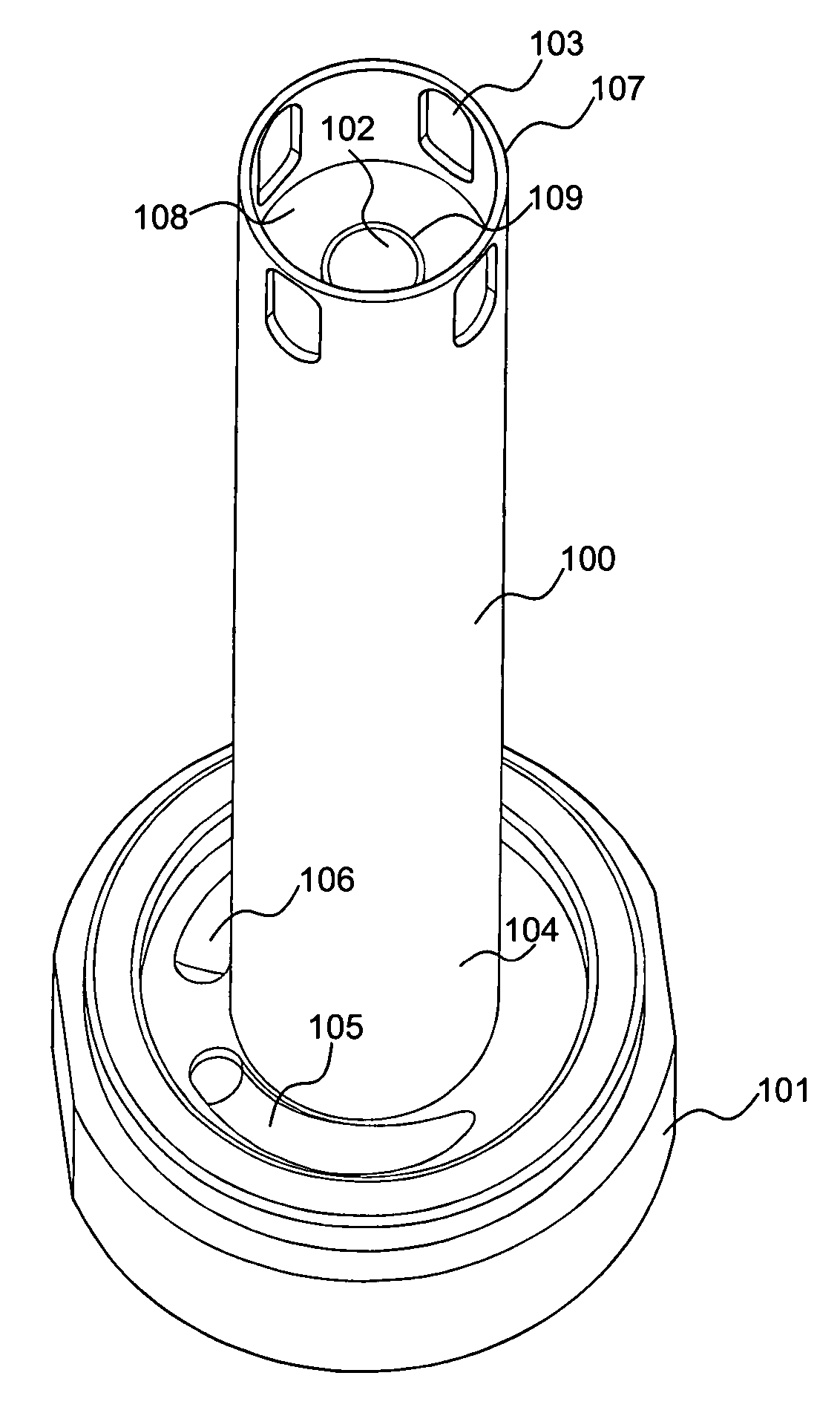
[0015] In a preferred embodiment, the magnetic core comprises an internal passage extending substantially the length of the magnetic core whereby the four columns of magnets are arranged around this internal passage. Preferably, this internal passage is lined with magnetic keepering means configured to inhibit or deaden the
magnetic field created by the magnets within the passage. The fluid flows from the inlet and into a contaminant capture zone defined by the outer surface of the magnetic core and an outer case. The fluid then flows in an opposition direction through the internal passage towards the outlet. Whilst the magnitude of the
magnet field within the catchment zone is greater than that within the internal passage, due to the nature and orientation of the columns of magnets, when the outer surface of the core becomes saturated with contaminant, unseparated contaminant within the fluid would otherwise be deposited within the internal passage leading to severe flow restriction and blockage. The magnetic keepering means significantly reduces and ideally eliminates the magnetic field within the internal passage. To assist cleaning and to prevent possible filter
corrosion the inner passage is further lined with a stainless steel inner sleeve extending the length of the passage.
[0017] In order to provide a magnetic core from which the contaminant material may be quickly and easily removed, the outer surface of the core (
metal sleeve) comprises a smooth and regular finish whereby an operator may simply remove the contaminant by, for example, wiping the outer surface with a cloth or scrapping tool. According, the filter of the present invention may be cleaned quickly and easily ready for reuse.
[0018] Preferably, the filter device comprises a filter head which is manufactured from anodised
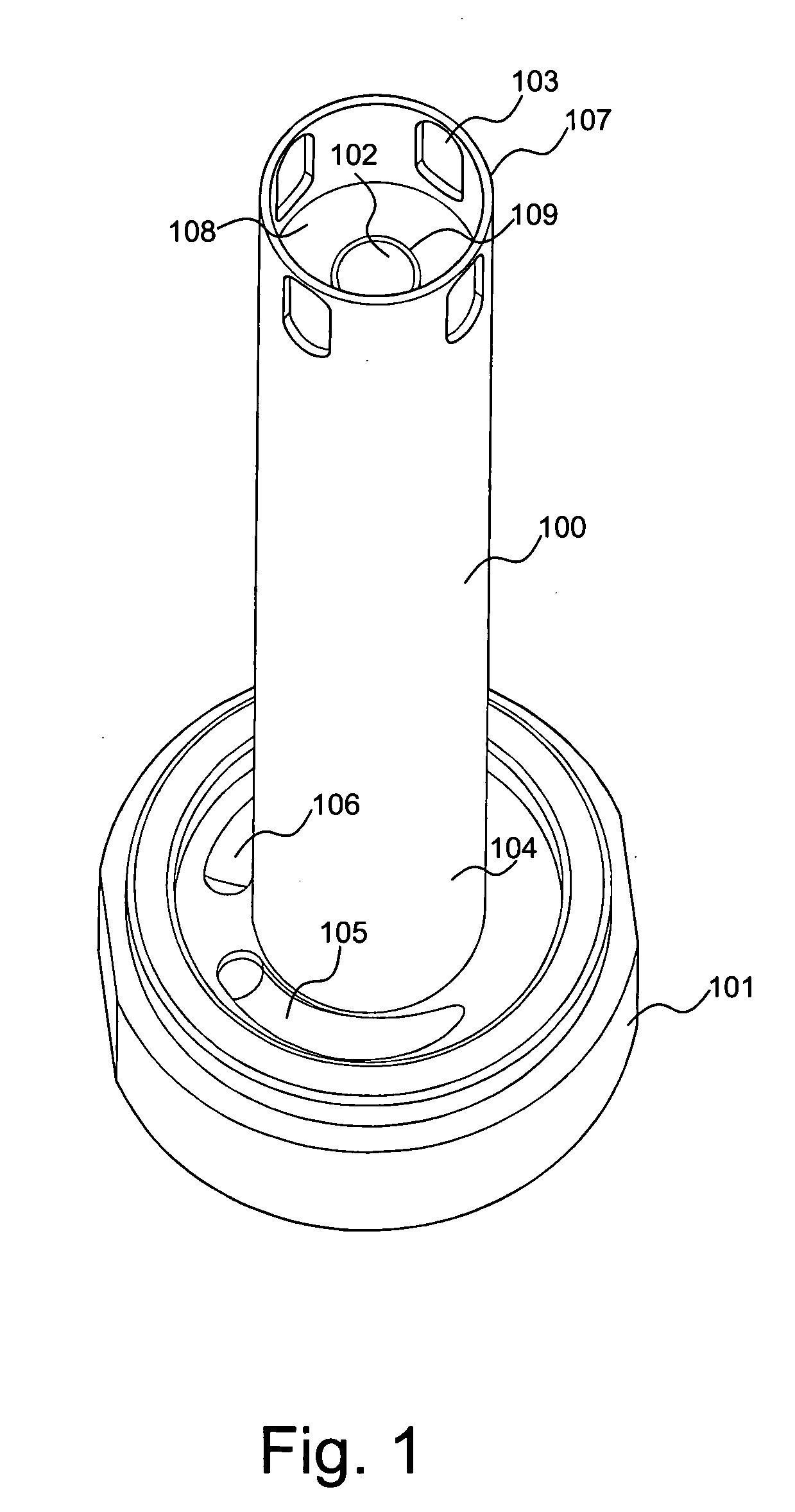
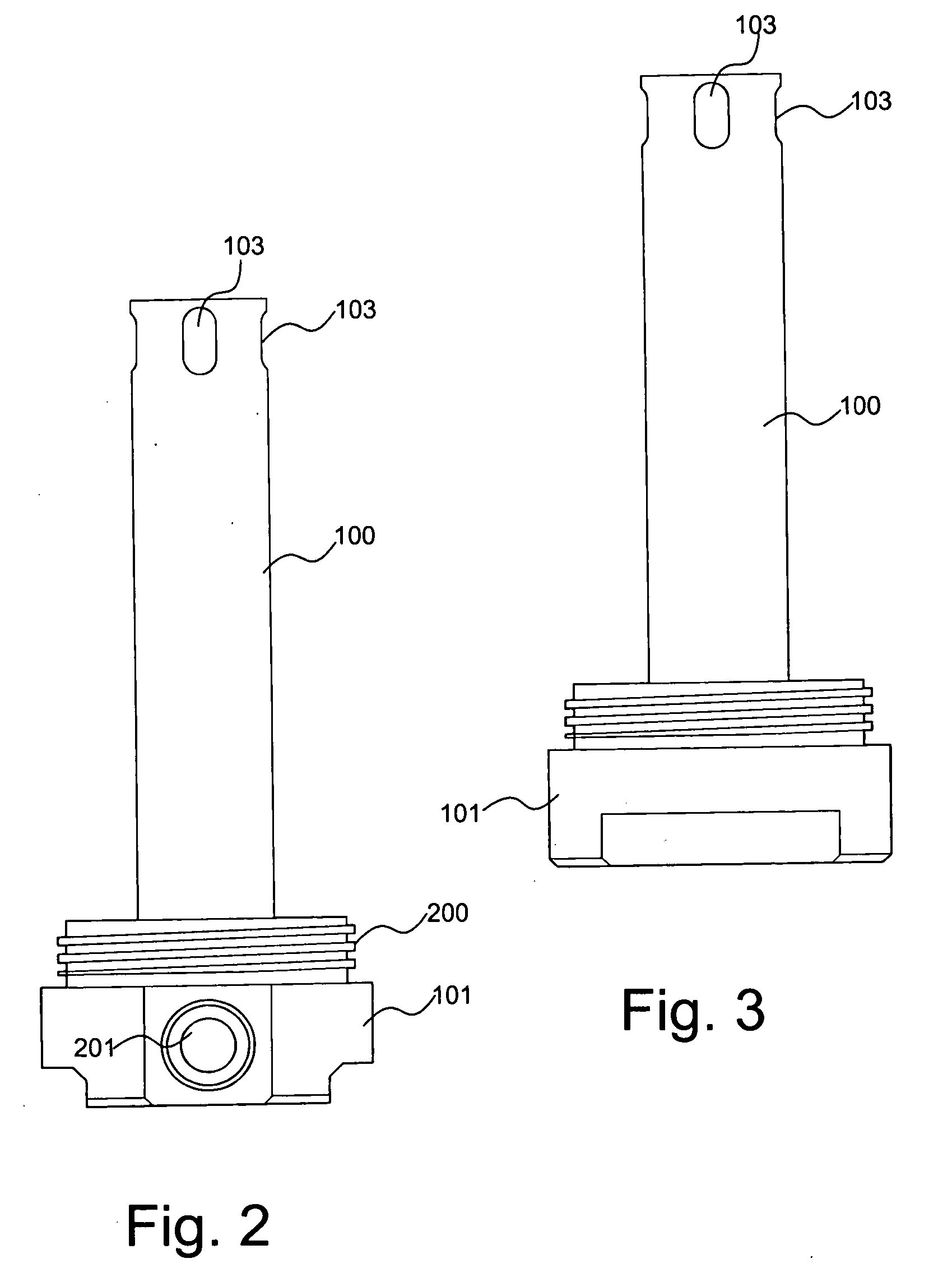
aluminium. The magnetic core may be removably attached to the filter head and preferably an o-ring is positioned at the interface between the filter head and the magnetic core to eliminate unfiltered fluid bypassing the catchment zone when flowing from inlet to outlet. The o-ring further serves to physically retain the magnetic core to the filter head whilst the outer case is secured to the filter head preferably by cooperating screw threads positioned at the filter head and outer case.
[0019] Preferably, the outer case, or at least a portion of the outer case is transparent or translucent enabling a user to visually determine the required time for maintenance or cleaning of the filter by observing the amount of contaminant deposited on the magnetic core. By using a transparent outer case the need to drain down the
system and remove the magnetic core from the device is avoided in turn reducing operational interruptions. So as to provide a uniform distribution of fluid through the contaminant catchment zone between the outer surface of the magnetic core and the inner surface of the outer case, the fluid inlet may be divided into a plurality of fluid directing ports to create a plurality of fluid flow paths within the catchment zone. Existing magnetic filters typically introduce the fluid into the filter via a single inlet whereby the fluid flow path within the catchment zone is directed substantially parallel with the length of the magnetic core. The linear flow path of known magnetic filters is disadvantages as the filter very quickly becomes saturated with contaminant at the fluid inlet
entry point causing restriction to flow and reduced
filtration efficiency. According to one aspect of the present invention, the incoming flow path is divided within the filter head, at the
entry point into the catchment zone. Preferably, the flow path is split into two tapered ports within the filter head configured to direct the inlet fluid to emerge into the catchment zone along a predetermined path such that the two
inlet flow paths collide at a predetermined distance along the length of the catchment zone causing
flow disruption and turbulence at and beyond the point of collision. This turbulence in the fluid flow serves to evenly distribute the deposition of contaminant over the entire magnetic core area resulting in enhanced volumes of contaminant separation, a greater
saturation level and higher
filtration efficiency. In particular, the plurality of inlets are configured to direct the flow of fluid into the catchment zone in a direction transverse to the longitudinal axis of the magnetic core.


