Welding head with heat-conducting structure for a gas welding gun

Inactive Publication Date: 2007-04-26
PRO ARIES INDS
View PDF2 Cites 0 Cited by
  • Summary
  • Abstract
  • Description
  • Claims
  • Application Information

AI Technical Summary

Benefits of technology

[0008] The primary objective of the present invention is to provide a welding head for a gas welding gun, wherein the heating effect of the heating member is substantially increased by improving the contacting area.
[0009] The secondary objective of the present invention is to provide a welding head for a gas welding gun, wherein the heat produced during gas combustion will be discharged via the air holes and then guided to flow in the direction of the guide slope, and thus it can overcome the conventional problem of damaging the neighboring electronic components.

Problems solved by technology

However, this conventional gas welding gun still has the following disadvantages:
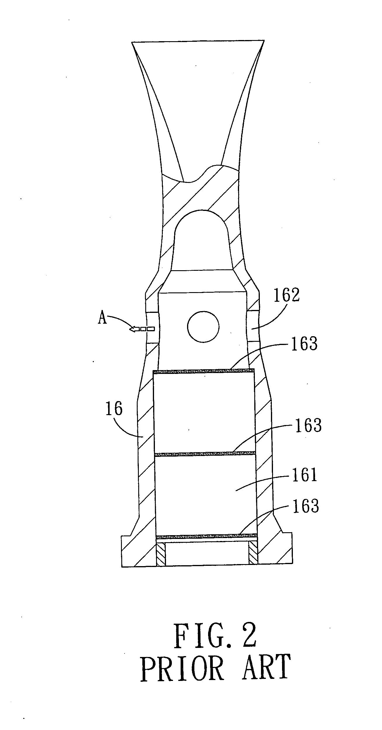
Second, the gas-combustion-produced hot air A is discharged from the air hole 162, plus electronic components nowadays are always arranged in a compact fashion, the discharge of hot air A will probably cause damage to neighboring electronic components.

Method used


Image

  • Welding head with heat-conducting structure for a gas welding gun
  • Welding head with heat-conducting structure for a gas welding gun
  • Welding head with heat-conducting structure for a gas welding gun

Examples


Embodiment Construction

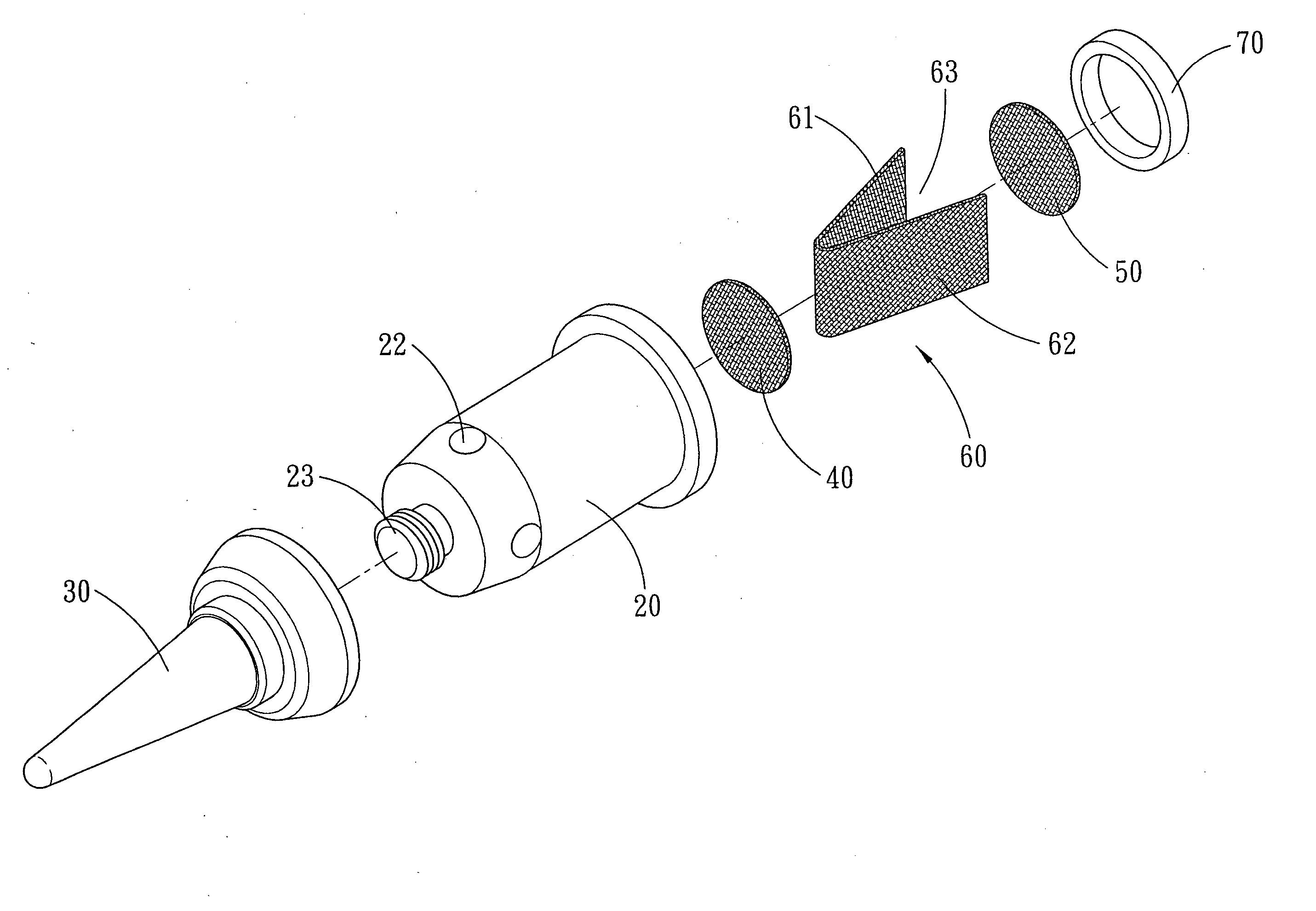
[0019] Referring to FIGS. 3 and 4, a welding head with heating-conducting structure for a gas welding gun in accordance with a preferred embodiment of the present invention is shown and comprises: a housing 20, a welding head 30, a tin net 40, a first net like heating member 50, a second net like heating member 60 and a positioning ring 70.

[0020] The housing 20 is formed with a recess 21 and four air holes 22 in communication with the recess 21. At an end of the housing 20 is formed a threaded portion 23.

[0021] The welding head 30 is cone shaped and has a threaded hole 31 to be screwed with the threaded portion 23 of the housing 20. The welding head 30 is further formed with a guiding slope 32 that is located correspondingly to the air holes 22 of the housing 20, and the space is left between the guiding slope 32 and the air holes 22 of the housing 20.

[0022] The tin net 40 is a flat net-like sheet received in the recess 21 of the housing 20.

[0023] The first net like heating memb...


PUM

PropertyMeasurementUnit
Electrical conductoraaaaaaaaaa
Areaaaaaaaaaaa

Abstract

A welding head with heat-conducting structure for a gas welding gun comprises: a housing, a welding head and a non-flat net-like heating member. The housing is formed with a recess and a plurality of air holes in communication with the recess. The welding head is installed on the housing and formed with a guiding slope being located correspondingly to the air holes of the housing, and between the guiding slope and the air holes of the housing is formed a space. The non-flat net-like heating member received in the recess of the housing. The heating effect of the heating member is substantially increased by improving the contacting area. The heat produced during gas combustion will be discharged via the air holes and then guided to flow in the direction of the guide slope, and thus it can be prevented from damaging the neighboring electronic components.

Description

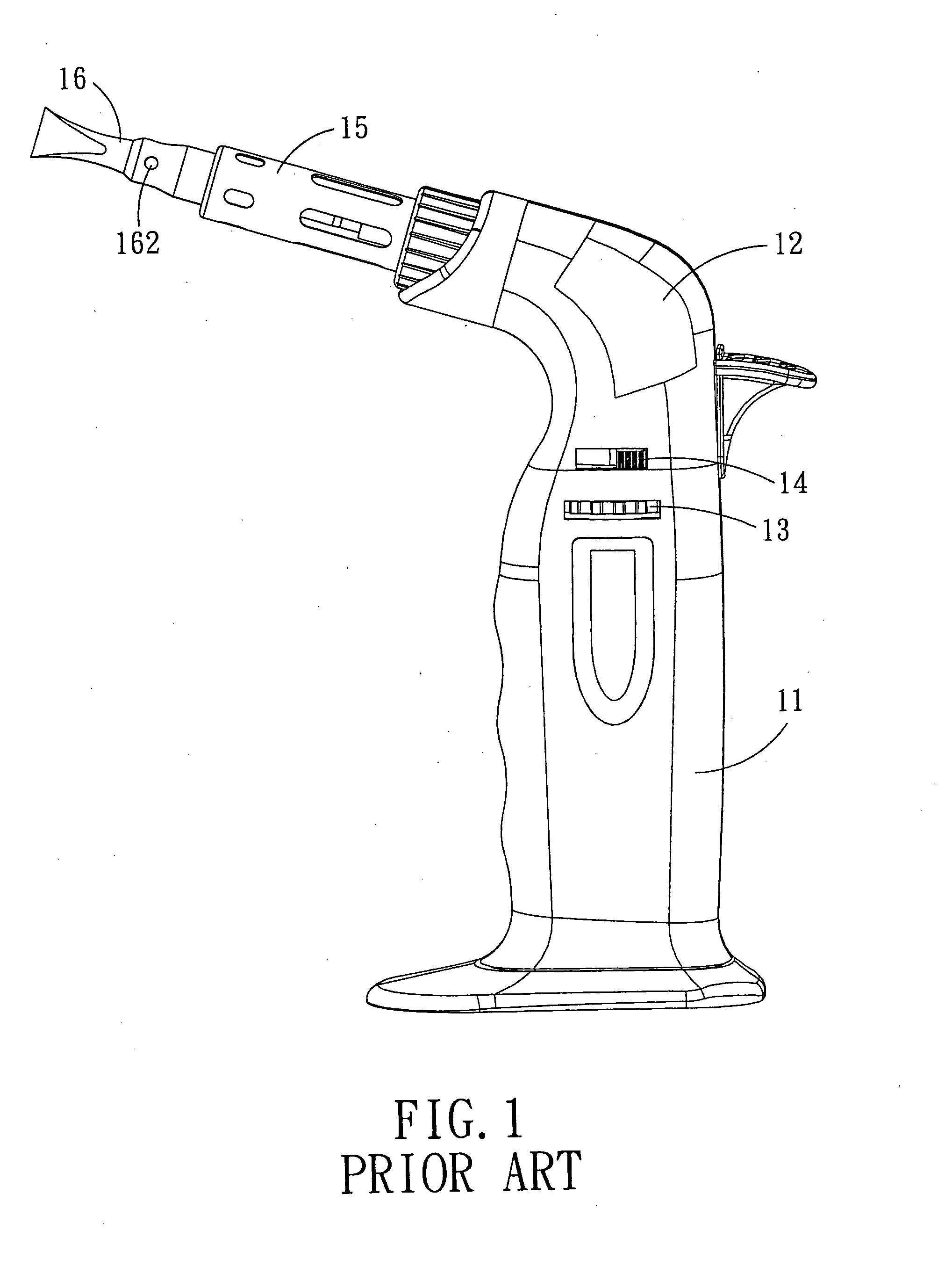
BACKGROUND OF THE INVENTION [0001] 1. Field of the Invention [0002] The present invention relates to a product of gas welding gun, and more particularly to a welding head with heat-conducting structure for a gas welding gun. [0003] 2. Description of the Prior Art [0004] Referring to FIG. 1, which shows a conventional gas welding gun comprising a gas container 11, a housing 12, an adjusting disc 13, a switch 14, a gas nozzle 15 and a welding head 16. As shown in FIG. 2, in the welding head 16 is formed a receiving recess 161 and an air hole 162 in communication with the receiving recess 161. In the receiving recess 161 are arranged three net-like heating members 163, when the mixture of gas and air is burned in the welding head 16, the heating members 163 will be heated to a very high temperature. And thus the welding head 16 is maintained at a high temperature for facilitating a welding operation. The heat or hot air A produced by the flaming gas can be discharged from the air hole ...

Claims


Application Information

Patent Timeline
IPC IPC(8): B23K1/00
CPCB23K5/22
Inventor LIN, TOMYLIN, KEVIN
Owner PRO ARIES INDS
Why Eureka
Try Eureka