
Wave power assembly

a technology of power assembly and wave power, applied in the direction of electric generator control, mechanical equipment, machines/engines, etc., can solve the problems of inferior conditions for energy conversion and the inability to successfully compete with conventional electric power production

Inactive Publication Date: 2007-04-26
SEABASED AB
View PDF11 Cites 19 Cited by
  • Summary
  • Abstract
  • Description
  • Claims
  • Application Information

AI Technical Summary

Benefits of technology

[0026] According to an additional preferred embodiment, the spring means is arranged to, at a motion amplitude corresponding to 90% of the maximum length of stroke of the rotor, exert a force, the size of which varies by a factor of 10 as a maximum. It is true that the advantages of the invention are profited to a large extent also when the range of force-variation limitation only constitutes approx. 50% of the maximum length of stroke, since the wave motions most often are within this range. Also when the wave motions are greater than so, the effect is still attained during the greater part of the motion. However, if the range of limitation of force variation is extended in accordance with this embodiment, the advantages of the invention will be possible to be fully profited also upon very strong wave motions.
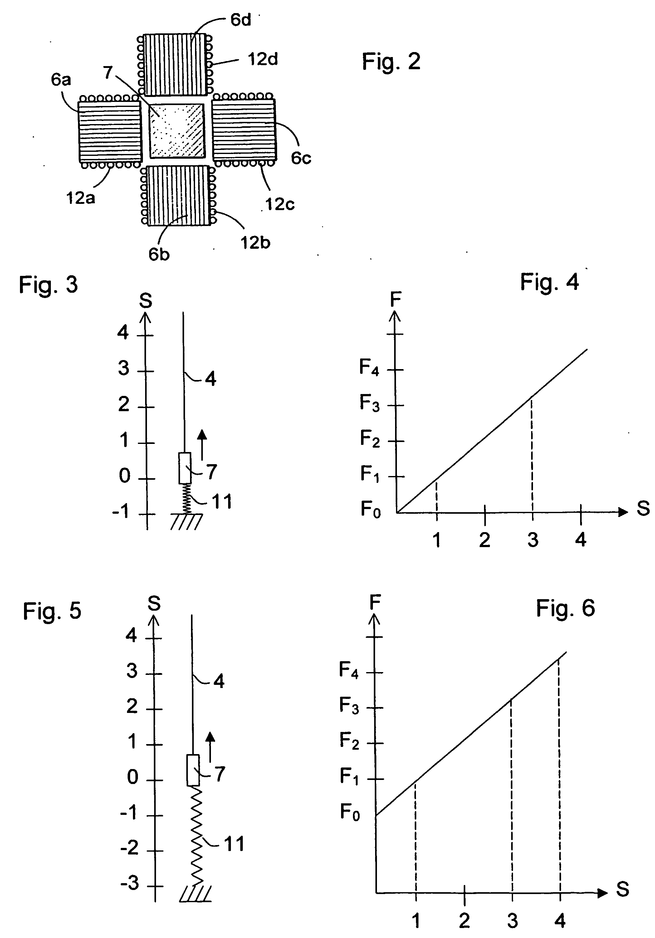
[0030] According to an additional preferred embodiment, the spring means has a non-linear spring characteristic. This facilitates the optimization of the force variation while taking other conditions, which influence the course of events, into consideration.
[0032] According to an additional preferred embodiment, the spring means comprises a plurality of springs. This is a simple method to provide the desired profile for the variation of the force.
[0033] According to an additional preferred embodiment, the spring means is arranged to, over a short distance next to the end position of the rotor that corresponds to the position of the hull on a crest of a wave, at the maximum length of stroke, exert a force that is many times greater than the maximum force below 90% of the maximum length of stroke of the rotor. Thereby, a powerful braking is attained of the upward motion of the rotor in the final phase thereof when the wave motion is such that the maximum length of stroke is utilized. By means of this braking, risks of damage are avoided in comparison with a stiff stop limiting the length of stroke.
[0035] According to an additional preferred embodiment, the force increases over said short distance with decreasing distance to the end position. The braking thereby becomes harmonious in that it to start with takes place smoothly and not until quite close to the end position with full strength.
[0036] According to an additional preferred embodiment, the spring means comprises one or more separate spring elements for applying force over said short distance. In case the spring force over said distance should differ considerably from the one during the rest of the motion, one or more separate elements is a simple and expedient way to achieve this.

Problems solved by technology

However, these have not succeeded to successfully compete with conventional electric power production.
When a simple mechanical tension spring is used, the conversion to electric energy will be effected non-uniformly, which creates disturbances and causes inferior conditions for the energy conversion.

Method used


Image

  • Wave power assembly
  • Wave power assembly
  • Wave power assembly

Examples


Embodiment Construction

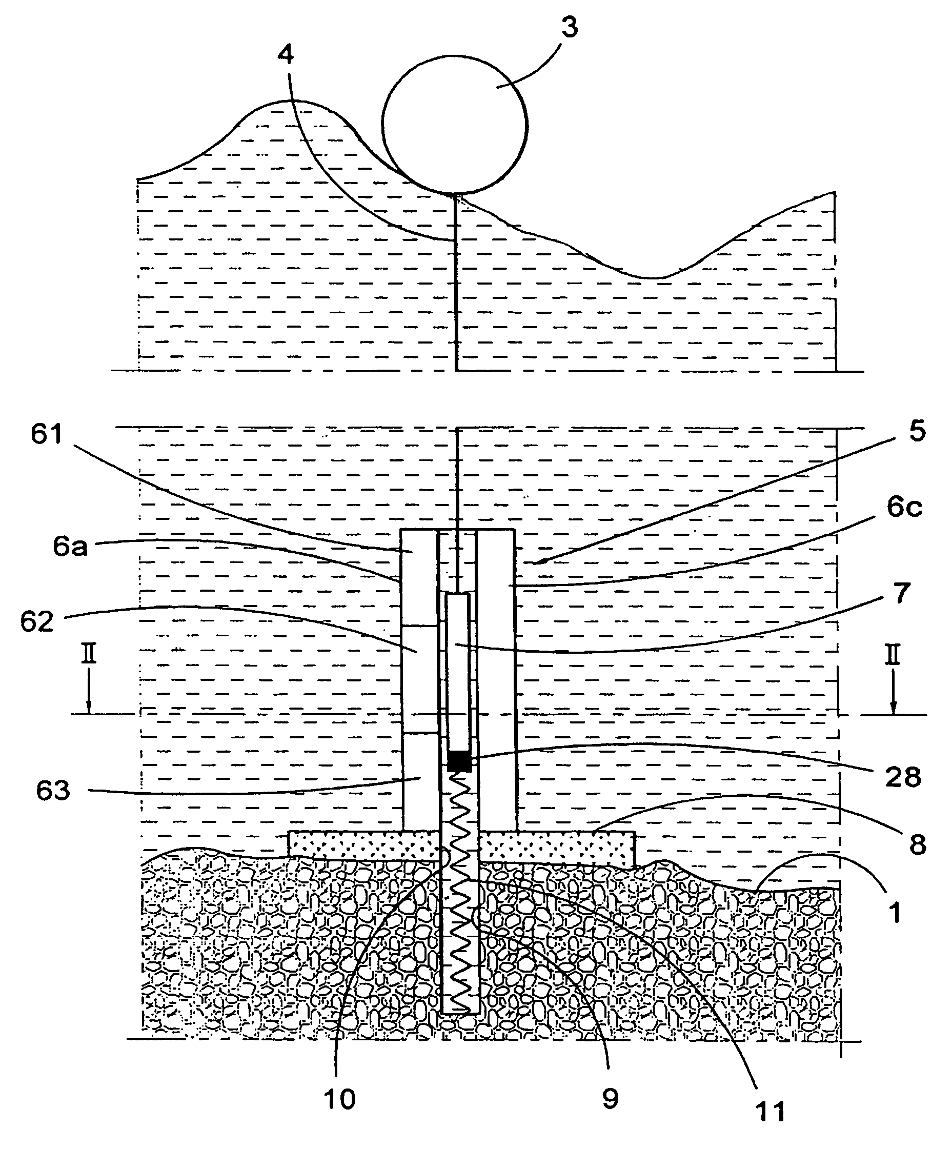
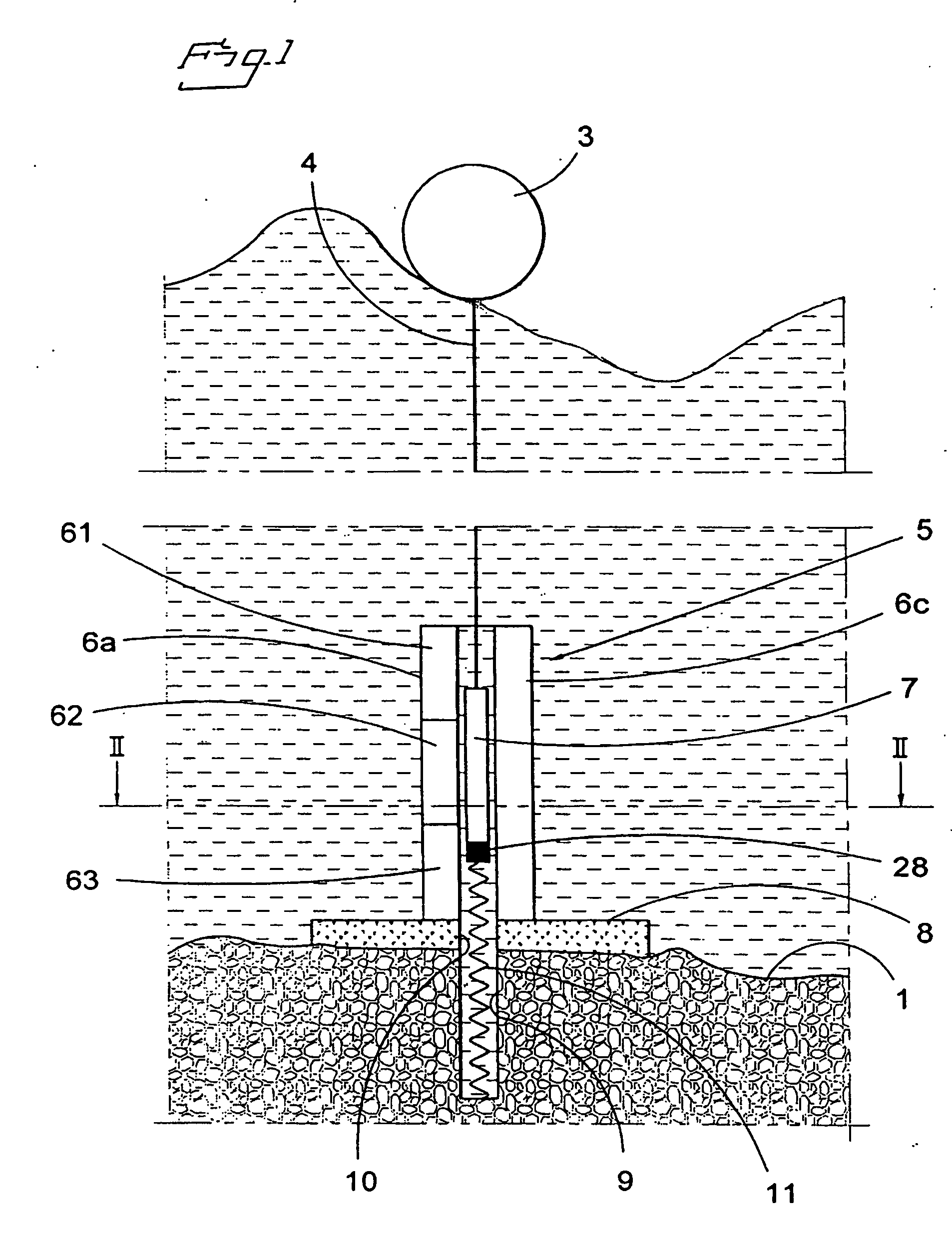
[0059]FIG. 1 illustrates the principle of a wave power assembly according to the invention. A hull 3 is arranged to float on the sea surface 2. Waves impart reciprocating vertical motion to the hull 3. At the bottom 1, a linear generator 5 is anchored via a base plate 8 fastened at the bottom, which plate may be a concrete slab. At the base plate 8, the stator 6a, 6c of the linear generator is fastened. The stator consists of four vertical column-like stator packs, only two of which are visible in the figure. In the space between the stator packs, the rotor 7 of the generator is arranged. The same is connected to the hull 3 by means of a line 4. The rotor 7 is of permanent magnetic material.

[0060] The base plate 8 has a centrally arranged hole 10, and concentrically therewith a bottom hole 9 is recessed in the bottom of the sea. The bottom hole 9 may suitably be lined. At the lower end of the bottom hole 9, a tension spring 11 is fastened, which with the other end thereof is fasten...


PUM


Abstract

A wave power assembly having a hull and a linear electric generator. The rotor is connected to the hull by connection means so that lifting force is transferred from the hull to the rotor. Spring means exert a force on the rotor that is counter-directed the lifting force. The spring means is arranged to, at a motion amplitude corresponding to 50% of the maximum length of stroke of the rotor, exert a force, the size of which varies by a factor of 2.5 as a maximum. The invention also relates to a wave power plant built up from wave power assemblies according to the invention. Furthermore, the invention relates to a use of the wave power assembly and a method for the generation of electric energy.

Description

FIELD OF THE INVENTION [0001] The present invention relates in a first aspect to a wave power assembly, comprising a hull and a linear electric generator, the rotor of which by means of connection means is connected to the hull and the stator of which is arranged to be anchored at a sea / lake bottom, which assembly also comprises spring means arranged to exert a force on the rotor, which force during at least a part of the motion of the rotor is counter-directed the lifting force exerted by the hull on the rotor, the rotor as a consequence of motions of the hull and the force exerted by the spring means being arranged to execute a reciprocating motion between two end positions defining the length of stroke of the rotor, the assembly being arranged for a fixed maximum length of stroke. The direction of motion of the rotor defines the longitudinal direction of the generator and a plane perpendicular to the direction of motion defines the cross direction of the generator. [0002] In a se...

Claims


Application Information

Patent Timeline
IPC IPC(8): F03B13/12F03B13/18
CPCF03B13/189Y02E10/38
Inventor LEIJON, MATSBERNHOFF, HANS
Owner SEABASED AB
Learn More