Piezoelectric fan

a technology of piezoelectric fans and fans, which is applied in the direction of machines/engines, generators/motors, liquid fuel engines, etc., can solve the problems of unnecessarily complex and costly assembly of prior art fans, and achieve the effect of convenient connection of piezoelectric materials and facilitate mounting of fans

Inactive Publication Date: 2007-04-26
PIEZO TECH
View PDF10 Cites 16 Cited by
  • Summary
  • Abstract
  • Description
  • Claims
  • Application Information

AI Technical Summary

Benefits of technology

[0006] Briefly describing one aspect of the present invention, there is provided a method of making a piezoelectric fan so that a portion of the fan blade material doubles as the substrate for the electronic circuit that powers and controls the fan. By this method a single component provides both the fanning portion and the electronic circuit portion of the fan. The single component may include flex circuitry at the electronic end, and may include devices such as bleed resistors, inductors, capacitors, DC to AC conversion, shielding, or even drive circuitry. A high-performance piezoelectric material that has a Curie temperature high enough to survive reflow soldering of the fan to an electronic device may be used to generate the fanning motion. The fan may include an interconnect to facilitate mounting the fan to an electronic device. The interconnect may also facilitate connecting the piezoelectric material to the electronic circuit of the fan, and the electronic circuit of the fan to the electrical system of the subject electronic device.

Problems solved by technology

Thus, prior art fans have been unnecessarily complex and costly to assemble.

Method used


Image

  • Piezoelectric fan
  • Piezoelectric fan
  • Piezoelectric fan

Examples


Embodiment Construction

[0011] For the purposes of promoting an understanding of the principles of the invention, reference will now be made to certain embodiments and specific language will be used to describe the same. It will nevertheless be understood that no limitation of the scope of the invention is thereby intended, such alterations and further modifications of the illustrated embodiments being contemplated as would normally occur to one skilled in the art to which the invention relates.

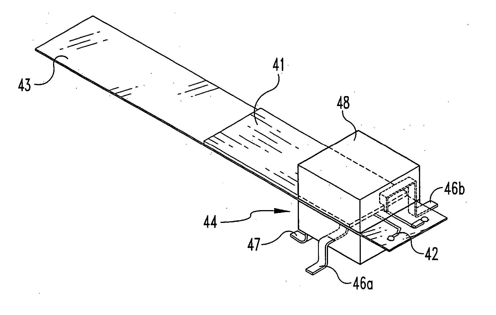
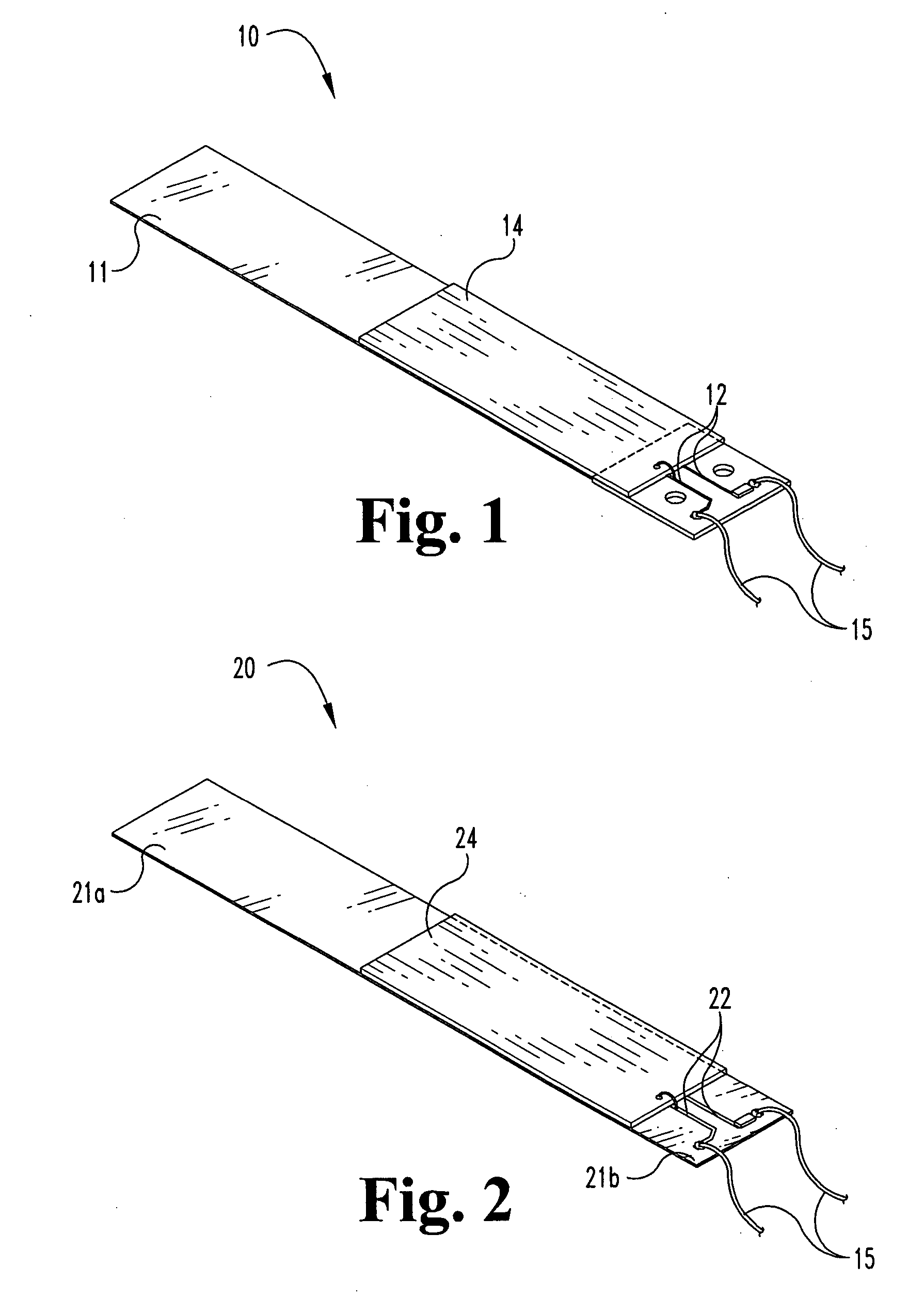
[0012] As indicated above, one aspect of the present invention relates to the use of a single piece of material as both a fan blade and as the substrate for the electronic circuit of a piezoelectric fan. The distal end of the fan blade functions normally, while the proximal end of the fan blade extends beyond the piezoelectric ceramic and forms the substrate on which an electronic circuit layout, traces, or other connection points can be made. This dual use of the blade material reduces part count and complexity—pr...


PUM

PropertyMeasurementUnit
Curie temperatureaaaaaaaaaa

Abstract

A method of making a piezoelectric fan includes using a portion of the fan blade material as the substrate for the electronic circuit. By this method a single material may serve as both the substrate for the electronic circuitry and as the fanning end of the fan blade. Flex circuitry, including elements such as bleed resistors, inductors, capacitors, DC to AC conversion, shielding, or even drive circuitry, may be used. The piezoelectric material used to power the fan blade may have a Curie temperature high enough to survive reflow soldering, thus allowing the fan to be surface mountable on an electronic device. The fan may include an interconnect to facilitate connecting the piezoelectric material to the electronic circuit of the fan, and to facilitate connecting the electronic circuit of the fan to the electrical system of an electronic device. The interconnect may also facilitate mechanically mounting the fan.

Description

FIELD OF THE INVENTION [0001] The present invention relates generally to piezo-electric fans, and more particularly to a piezoelectric fan having a simplified and improved construction. BACKGROUND TO THE INVENTION [0002] Piezoelectric fans are typically composed of one or more pieces of piezoelectric ceramic laminated to a metal or polymer blade. The lamination can be done with a stack of ceramic on one side of the fan blade, or on both sides of the fan blade. The ceramic can be wired in a series or parallel configuration requiring one or more positive and negative leads. [0003] A small electric circuit may be used to aid in the interconnection of the piezoceramic. Various electronic devices (surface mount or otherwise) such as bleed resistors, inductors, capacitors, DC to AC conversion, or even drive circuitry, may also be included. Ultimately, an AC excitation signal is usually applied to the ceramic. This causes the ceramic to flex in a back and forth bending motion. The fan blad...

Claims


Application Information

Patent Timeline
Patent Type & Authority Applications(United States)
IPC IPC(8): H01L41/00
CPCF04D29/023F04D29/26F04D33/00H01L41/094F05D2300/43F05D2300/50F05D2300/434F05D2300/603F05D2230/31F05D2300/20F05D2300/222H10N30/2042
Inventor MORRIS, GRANT ADAMBROSCH, JARED ROBERT
Owner PIEZO TECH
Why Eureka
Try Eureka