Step sinusoidal voltage controlling method for hid, flourescent and incandescent light dimming applications

Inactive Publication Date: 2007-04-26
POWER CONTROL TECH
View PDF8 Cites 0 Cited by
  • Summary
  • Abstract
  • Description
  • Claims
  • Application Information

AI Technical Summary

Benefits of technology

[0004] Although adjusting the output voltage in steps may be generally known for some applications, there are a number of loads, such as a High Pressure Sodium (HPS) Ballast, that do not accept this type of voltage control. Indee

Problems solved by technology

Although adjusting the output voltage in steps may be generally known for some applications, there are a num

Method used


Image

  • Step sinusoidal voltage controlling method for hid, flourescent and incandescent light dimming applications
  • Step sinusoidal voltage controlling method for hid, flourescent and incandescent light dimming applications
  • Step sinusoidal voltage controlling method for hid, flourescent and incandescent light dimming applications

Examples


Example

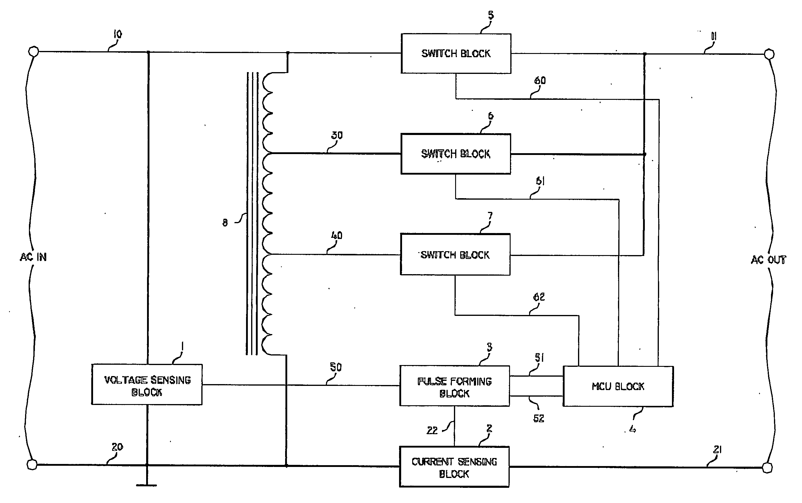
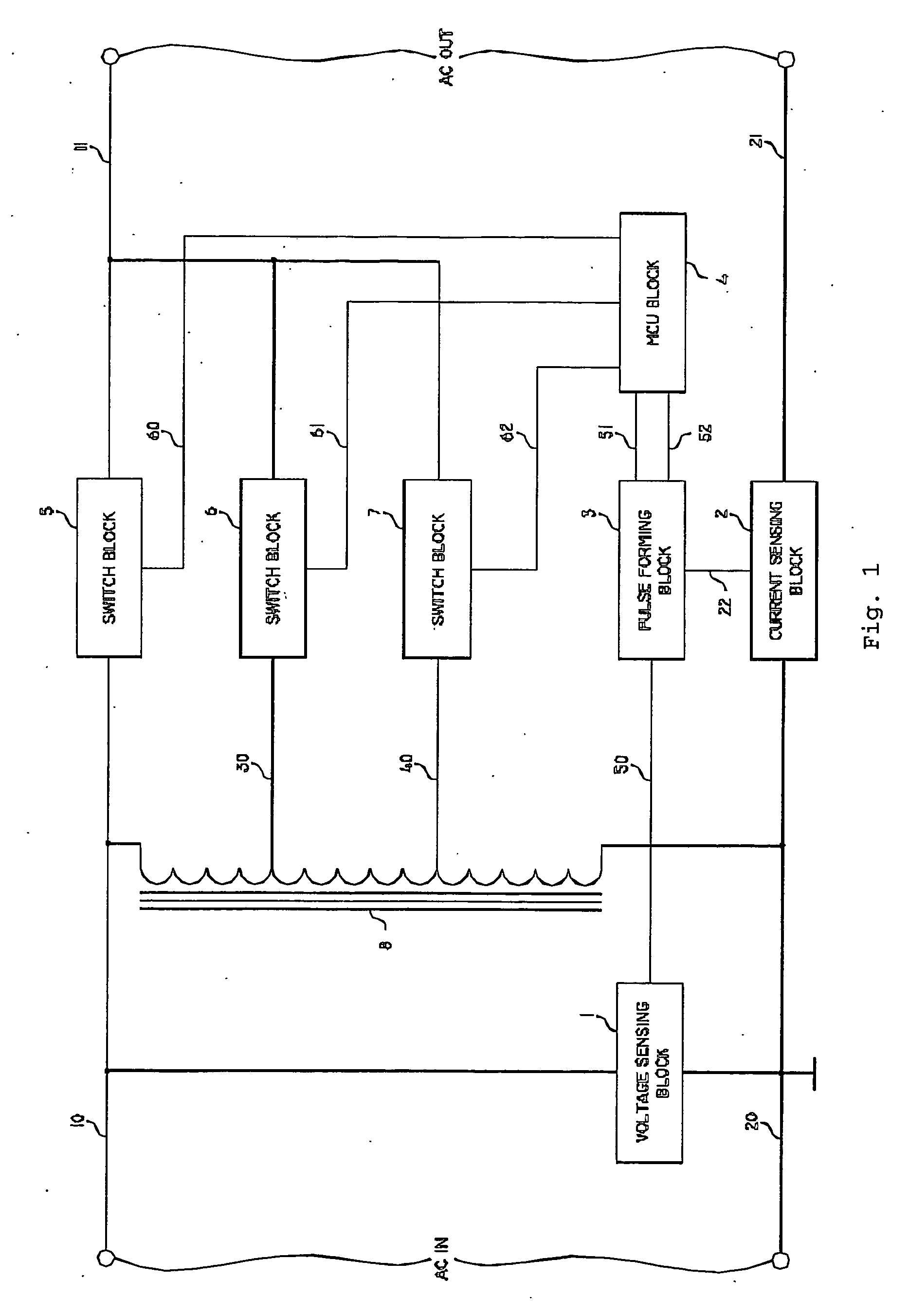
[0012] An embodiment of the invention is illustrated in FIG. 1, and this device includes a multiple tap step-down autotransformer 8, voltage sensing block 1, current sensing block 2, pulse forming block 3, MCU block 4 and switch blocks 5, 6 and 7. As this embodiment is energized, MCU block 4 generates a command signal on line 60 for turning on switch block 5. This means that the step voltage controlling device always starts at full output voltage measured between lines 11 and 21, a voltage that is equal to the voltage measured between lines 10 and 20. It is generally known that a HID ballast must be first energized at its nominal voltage, and it must continue to operate at the nominal voltage until it reaches its normal operating parameters. This period of time when the HID ballast must first operate at nominal voltage is known as “lamp warm-up time”.

[0013]FIG. 5 indicates the voltage / current phase angle for a HID ballast. When the ballast is first energized, the voltage current ph...


PUM


Abstract

A step voltage controlling device and method for High Intensity Discharge (HID) light dimming applications includes an autotransformer, voltage sensing block, current sensing block, pulse forming block, microprocessor control unit (MCU) block and plural three switch blocks which allows an instantaneous variation of the voltage applied to the load which is controlled to be synchronized with the load current zero crossing point.

Description

FIELD OF THE INVENTION [0001] This disclosure relates to alternating current voltage controllers, more particularly to controllers for varying the AC voltage applied to a large variety of lighting loads, including, but not limited to all types of gas discharge lamps as well as incandescent lamps. This application claims priority under the Paris Convention to U.S. Provisional Application for Patent Ser. No. 60 / 481,804 filed on Dec. 17, 2004, the entire contents of which are incorporated herein by reference. BACKGROUND [0002] A number of electronic high frequency switching AC voltage controllers have been devised for delivering a variable sinusoidal output voltage. U.S. Pat. No. 5,018,058 discloses how to obtain a pure sinusoidal output voltage waveform from the AC line voltage using switchmode electronic circuitry. Furthermore, U.S. Pat. Nos. 5,500,575 and 5,714,847 show other methods of obtaining a variable AC output voltage having a sinusoidal waveform. Although existing electronic...

Claims


Application Information

Patent Timeline
IPC IPC(8): H05B41/24G01RH02M5/257
CPCH02M5/257H05B39/08H05B41/231H05B41/2885H05B41/40Y02B20/202Y02B20/00
Inventor IONESCU, ADRIAN F.
Owner POWER CONTROL TECH
Why Eureka
Try Eureka