Power adapter for power tools

a power tool and power adapter technology, applied in the field of power tools, can solve the problems of affecting the overall size and shape of the overall size and shape of the battery, the relatively high cost of the battery cartridge, and the limited power available of the battery operated power tool

Inactive Publication Date: 2007-04-26
NORRIS WAATANI
View PDF5 Cites 40 Cited by
  • Summary
  • Abstract
  • Description
  • Claims
  • Application Information

AI Technical Summary

Benefits of technology

[0007] The power adapter further comprises electrical connections adapted to connect to the electrical connections of the cordless power tool which normally couple to the electrical connections of the battery cartridge. Accordingly, the power adapter is contained in a housing which is configured to couple to the power tool in substantially the same or similar manner as the battery cartridge which the adapter replaces. In a further innovative aspect of the present invention, the power adapter housing may also have substantially the same overall size and shape as the battery cartridge which it replaces. In this way, the power adapter maintains substantially the same ergonomics such as balance and size as the cordless power tool with the battery cartridge. The power adapter also has a power cord extending from the housing which can be plugged into a standard AC electrical power outlet.

Problems solved by technology

On the downside, battery-operated power tools have a limited amount of power available before the battery(ies) must be replaced or re-charged.
Accordingly, the battery cartridges are relatively expensive and it is usually cost prohibitive for a user to have more than two or three batteries for any cordless power tool.
Moreover, it typically takes much more time to charge the battery cartridge than the amount of time that the power tool can be operated on a single charge.
But this requires the user to purchase and have available at the work site an extra power tool, which may be an expensive and inconvenient proposition.

Method used


Image

  • Power adapter for power tools
  • Power adapter for power tools

Examples


Embodiment Construction

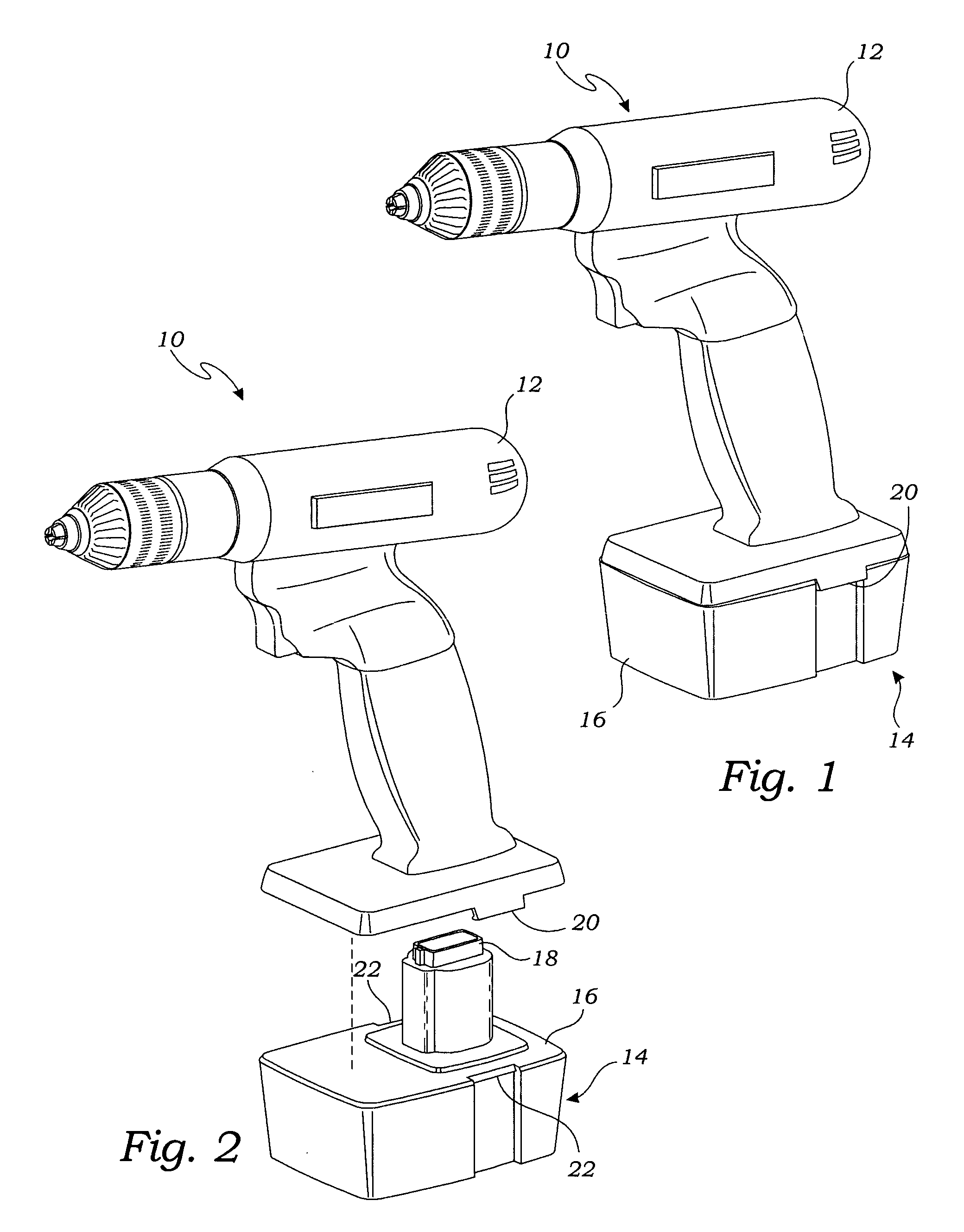
[0014] Turning to FIG. 1 and FIG. 2, an exemplary cordless power tool 10, in this case a cordless power drill, is shown. It is should be understood that the cordless power tool can be any type of power tool, including without limitation all of the power tools described above.

[0015] The power drill 10 includes a main body 12 and a battery cartridge 14. The battery cartridge 14 is removable from the main body 12 as shown in FIG. 2. The battery cartridge 14 includes a housing 16 and a battery contact 18. The battery contact 18 comprises at least two electrical connections which function as the positive and negative terminals of the battery cartridge. The battery electrical contact 18 couples to a power tool contact (not shown) provided in the main body 12 when the battery cartridge 14 is installed on the main body 12.

[0016] In the exemplary power tool of FIGS. 1 and 2, the battery cartridge 14 is retained on the main body 12 by a pair of releasable clasps 18 which releasably engage m...


PUM


Abstract

A power adapter for powering battery-operated (also referred to as “cordless”) power tools using electricity from a standard AC electrical outlet. Cordless power tools are typically powered by a battery cartridge which is removeably attached to the power tool. The battery cartridge includes a housing which contains the battery cells and electrical connections for electrically connecting the battery cartridge to the power tool. The power adapter of the present invention replaces, at least temporarily, the battery cartridge and comprises a housing which contains a transformer for converting the alternating (AC) electrical current to the same direct current (DC) electrical power provided by the battery cartridge. The power adapter further comprises electrical connections adapted to connect to the electrical connections of the cordless power tool. The power adapter housing has substantially the same overall size and shape as the battery cartridge which it replaces. The power adapter also has a power cord electrically connected to the input of the transformer and which extends from the housing and which can be plugged into a standard AC electrical power outlet.

Description

[0001] In accordance with 35 U.S.C. Section 119(e), and any other applicable laws, this application claims the benefit of U.S. Provisional Application No. 60 / 726,231, filed Oct. 14, 2005. The contents of the aforementioned provisional application is incorporated by reference in its entirety as if set forth fully herein.FIELD OF THE INVENTION [0002] The present invention relates generally to the field of power tools, and more particularly to an AC to DC power adapter (transformer and / or converter) for powering battery-operated power tools using a standard AC electrical outlet. BACKGROUND OF THE INVENTION [0003] Numerous power tools utilize batteries as their primary power source and are commonly referred to as “cordless” because they do not require a cord for connection to an alternating current (AC) electrical outlet. Such power tools include drills, drivers, impact drivers / wrenches, circular saws, reciprocal saws, jig saws, lighting equipment, vacuums, and also many lawn & garden p...

Claims


Application Information

Patent Timeline
Patent Type & Authority Applications(United States)
IPC IPC(8): H02J7/00
CPCH02J7/0045
Inventor NORRIS, WAATANI
Owner NORRIS WAATANI
Why Eureka
Try Eureka