Liquid crystal display device

Active Publication Date: 2007-04-26
JAPAN DISPLAY CENT INC
View PDF3 Cites 14 Cited by
  • Summary
  • Abstract
  • Description
  • Claims
  • Application Information

AI Technical Summary

Benefits of technology

[0013] The object of the present invention is to provide a liquid crystal display device which can i

Problems solved by technology

In the conventional MVA mode, however, the compensation of the viewing angle at the time of displaying intermediate gradations or white is insufficient, and the gradation characteristics are different bet

Method used


Image

  • Liquid crystal display device
  • Liquid crystal display device
  • Liquid crystal display device

Examples


first embodiment

( Sub-Pixel Structure)

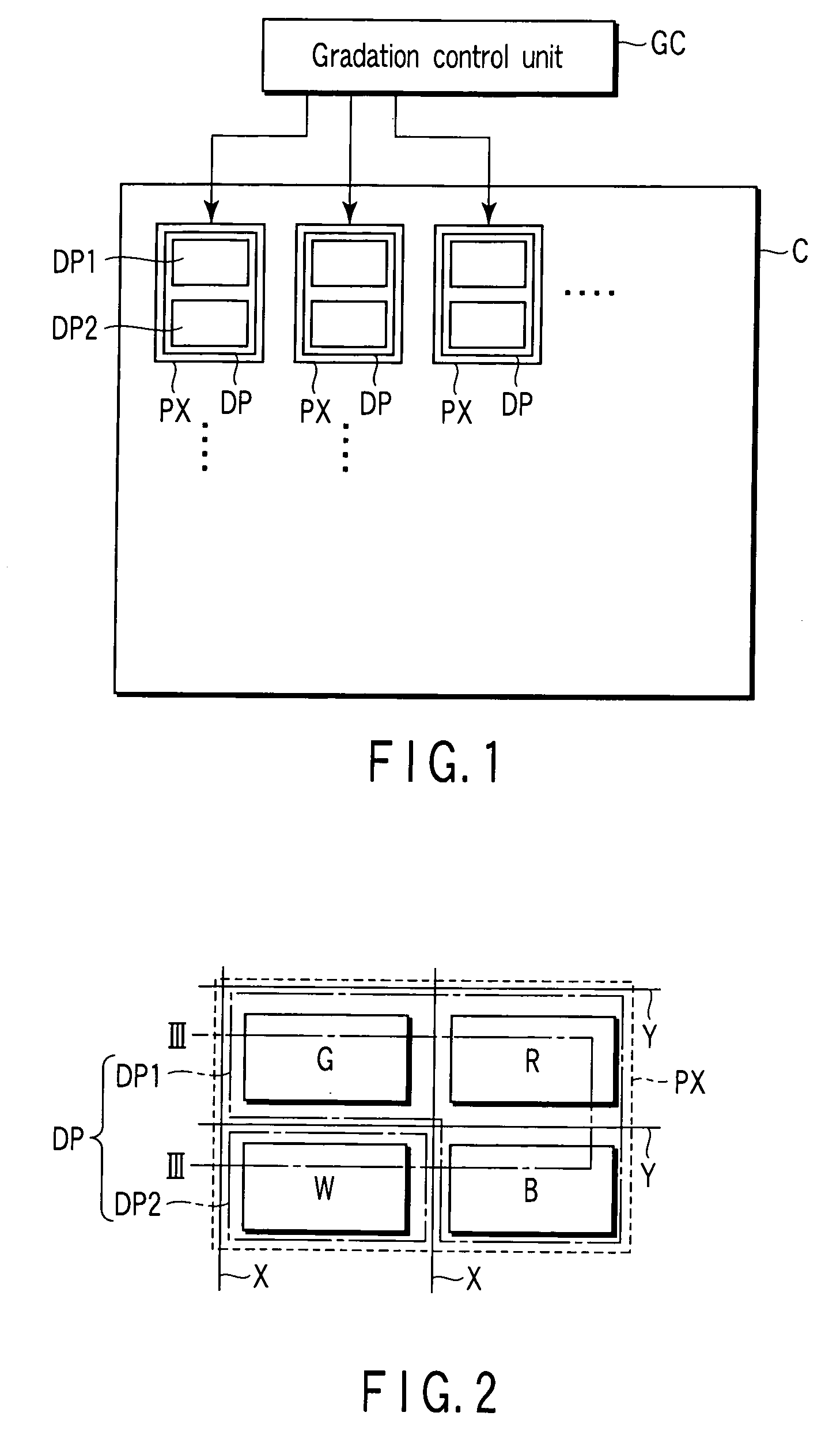
[0046] In a first embodiment, the display section that is disposed in each pixel PX is configured to include a plurality of sub-pixels. In other words, one pixel is composed of these sub-pixels. The first embodiment will be described below, by referring to first to third examples of structure.

>

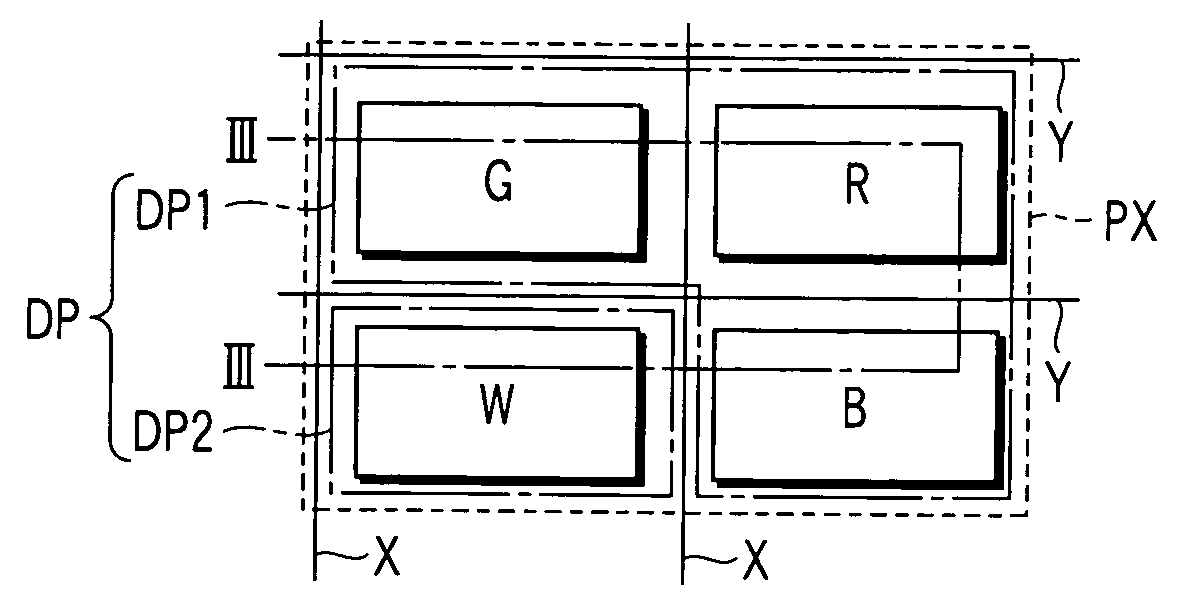
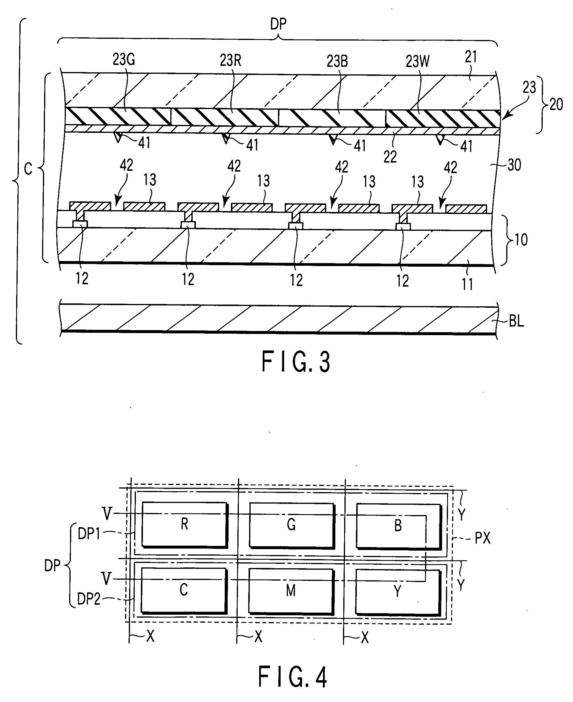
[0047] As is shown in FIG. 2, in a liquid crystal display device according to a first example of structure, each pixel PX has a display section DP comprising a first white display structure DP1 and a second white display structure DP2. The first white display structure DP1 is composed of sub-pixels of the primary colors. In the example shown in FIG. 2, the first white display structure DP1 is composed of three sub-pixels of red (R), green (G) and blue (B). Alternatively, the first white display structure DP1 may be composed of three sub-pixels of cyan (C), magenta (M) and yellow (Y). The second white display structure DP2 is composed of a single sub-pixel of white (W). I...

example 1

Circular-Polarization-Based MVA Mode

[0088] Next, Example 1, in which the first embodiment is applied, is described. As is shown in FIG. 13, a liquid crystal display device according to Example 1 is a liquid crystal display device of a circular-polarization-based vertical alignment mode in which liquid crystal molecules in each pixel are aligned substantially vertical to the major surface of the substrate in a voltage-off state. The liquid crystal display device comprises a circular polarizer structure P, a variable retarder structure VR, a circular analyzer structure A and a backlight BL which emits white light.

[0089] The variable retarder structure VR includes a dot-matrix liquid crystal cell C in which a liquid crystal layer is held between two electrode-equipped substrates. Each pixel may be formed with the structure of any one of the first to third examples of structure. Each pixel is divided into two domains.

[0090] The circular polarizer structure P is disposed on the backli...

example 2

Linear-Polarization-Based MVA Mode

[0102] Next, Example 2, in which the first embodiment is applied, is described. As is shown in FIG. 15, a liquid crystal display device according to Example 2 is a liquid crystal display device of a linear-polarization-based vertical alignment mode in which liquid crystal molecules in each pixel are aligned substantially vertical to the major surface of the substrate in a voltage-off state. The liquid crystal display device comprises a circular polarizer structure P, a variable retarder structure VR, a circular analyzer structure A and a backlight BL which emits white light. The structural parts common to those in Example 1 are denoted by like reference numerals, and a detailed description thereof is omitted.

[0103] The variable retarder structure VR includes a dot-matrix liquid crystal cell C in which a liquid crystal layer is held between two electrode-equipped substrates. Each pixel may be formed with the structure of any one of the first to thi...


PUM


Abstract

A liquid crystal display device includes a display section which enables color display in each of pixels, and a gradation control unit which controls a gradation level in each of the pixels. The display section includes a first white display structure which is configured to combine primary colors and to display white, and a second white display structure which is configured to include a color with a chromaticity different from a chromaticity of the primary color of the first white display structure and to display white. The gradation control unit has a first control mode in which the gradation level of each pixel is controlled by one of the first white display structure and the second white display structure, and a second control mode in which the gradation level of each pixel is controlled by a combination of the first white display structure and the second white display structure.

Description

CROSS-REFERENCE TO RELATED APPLICATIONS [0001] This application is based upon and claims the benefit of priority from prior Japanese Patent Application No. 2005-306882, filed Oct. 21, 2005, the entire contents of which are incorporated herein by reference. BACKGROUND OF THE INVENTION [0002] 1. Field of the Invention [0003] The present invention relates generally to a liquid crystal display device, and more particularly to a dot-matrix-type liquid crystal display device which can perform color display. [0004] 2. Description of the Related Art [0005] A liquid crystal display device has various features such as thickness in size, light weight, and low power consumption. The liquid crystal display device is applied to various uses, e.g. OA equipment, information terminals, timepieces, and TVs. In particular, a liquid crystal display device comprising thin-film transistors (TFTs) has high responsivity and, therefore, it is used as a monitor of a mobile TV, a computer, etc., which display...

Claims


Application Information

Patent Timeline
IPC IPC(8): G09G3/36
CPCG02F1/13306G09G3/3607G09G2300/0452G09G2310/0235G09G2320/028
Inventor HISATAKE, YUUZO
Owner JAPAN DISPLAY CENT INC
Why Eureka
Try Eureka