Microinjection apparatus with thermochromic indicator

a technology of thermochromic indicator and injection apparatus, which is applied in the direction of printing, other printing apparatus, etc., can solve the problems of inability of prior art sensing system to detect the heating efficiency of ink-jet head, difficulty in calibration, and need to dispose of extra apparatus

Inactive Publication Date: 2007-04-26
BENQ CORP
View PDF3 Cites 1 Cited by
  • Summary
  • Abstract
  • Description
  • Claims
  • Application Information

AI Technical Summary

Benefits of technology

[0015] The advantage and spirit of the invention may be understood by the following recitations together with the appended drawings.

Problems solved by technology

However, the sensing system of the prior art is not capable of detecting the heating efficiency of the ink-jet head.
However, problems arise because of sensor design, the difficulties of calibration, and changes due to mounting stress, encapsulation shifts, vibration, noise and other influences.
Furthermore, to perform the heating efficiency test, extra apparatus have to be disposed, even the processes have to be stopped.
Obviously, the production cost and time are both elevated by these test processes.

Method used


Image

  • Microinjection apparatus with thermochromic indicator
  • Microinjection apparatus with thermochromic indicator
  • Microinjection apparatus with thermochromic indicator

Examples


Embodiment Construction

[0021] The present invention provides a microinjection apparatus with thermochromic indicator. The preferred embodiment according to the present invention is disclosed as follow.

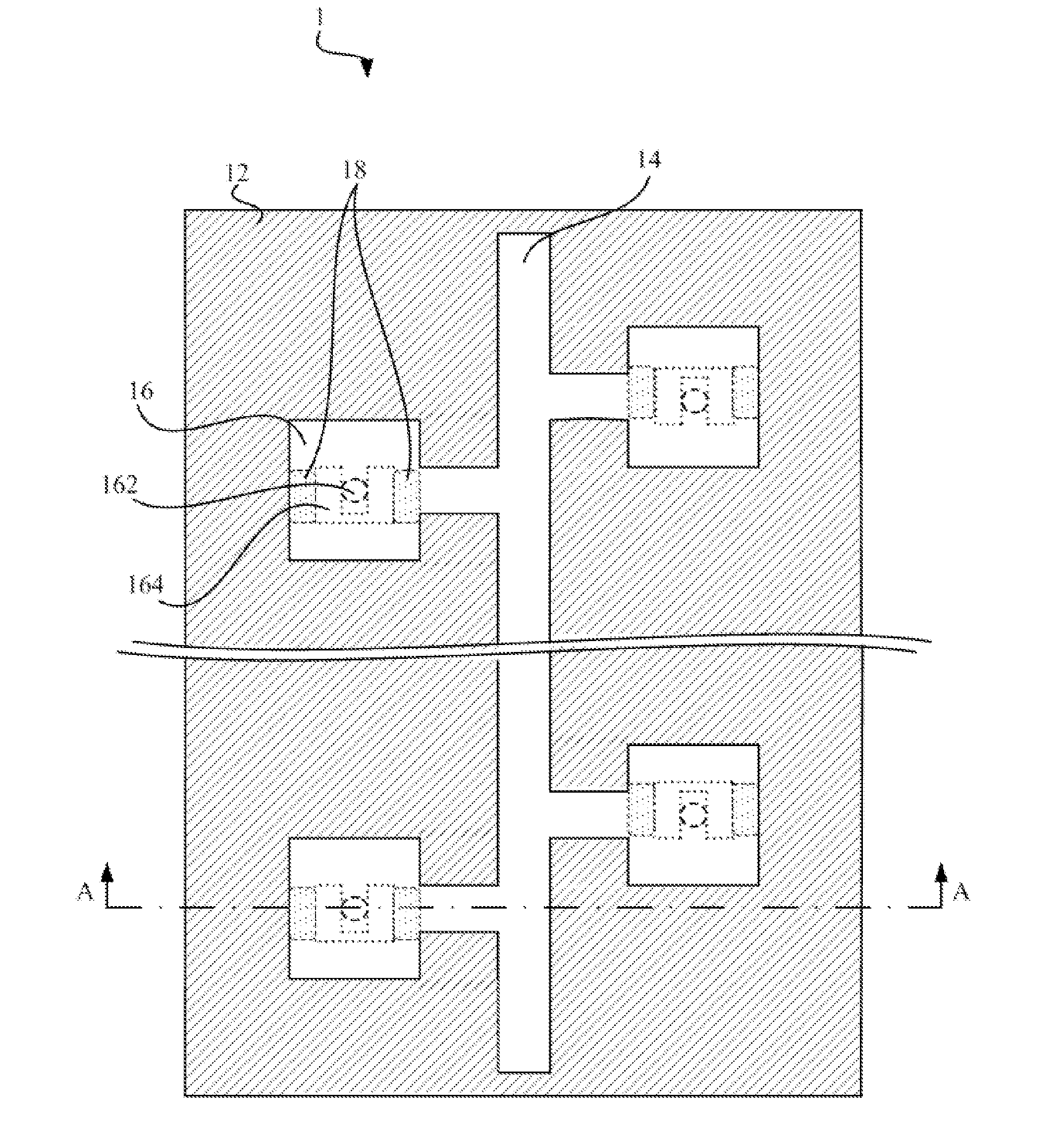
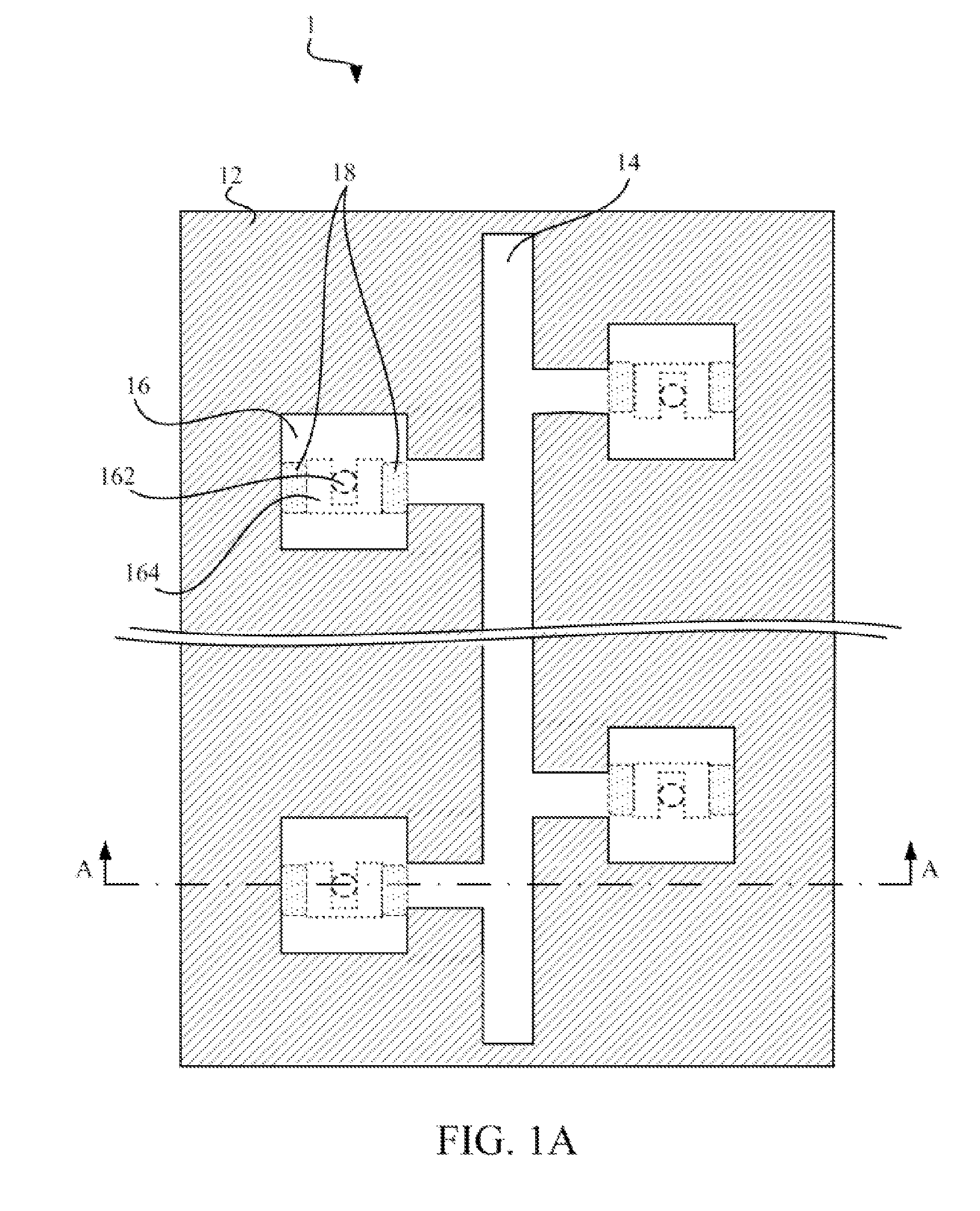
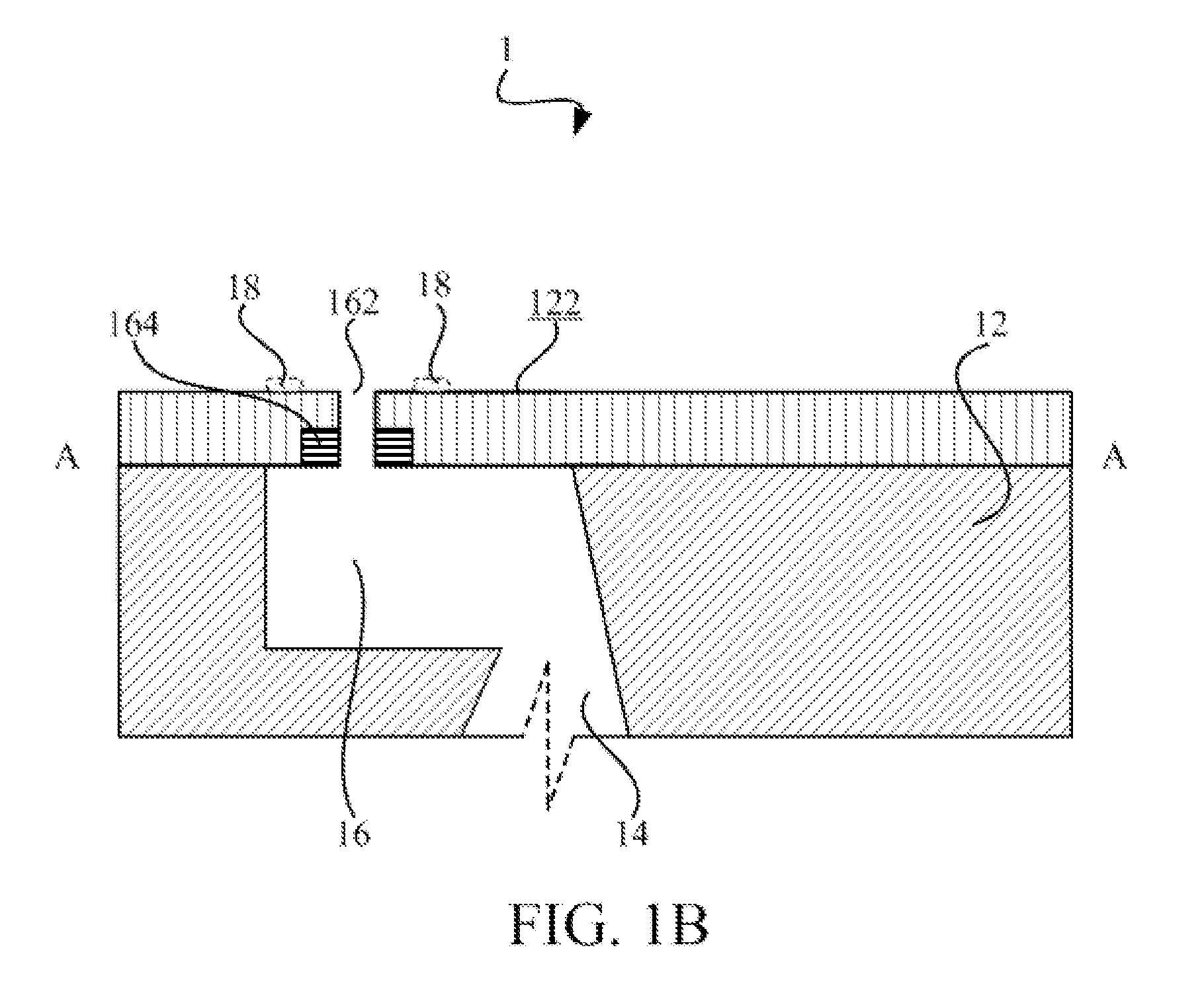
[0022] Referring to FIG. 1A and FIG. 1B, which show a microinjection apparatus 1 for a fluid according to a preferred embodiment of the present invention. FIG. 1A is a plan view of the microinjection apparatus 1, whereas FIG. 1B is a sectional view along line A-A of the microinjection apparatus 1 shown in FIG. 1A, to illustrate the corresponding position of each device within the microinjection apparatus 1.

[0023] As shown in FIG. 1A and FIG. 1B, the microinjection apparatus 1 of the present invention includes a substrate 12, a manifold 14, a plurality of fluid chambers 16 and a plurality of thermal sensing films 18.

[0024] In addition, the manifold 14 is formed on the substrate 12 for containing the fluid (not shown) therein, and further supplying the fluid to the fluid chambers 16. The fluid chambers 16 a...


PUM


Abstract

The invention provides a microinjection apparatus for a fluid. The microinjection apparatus comprises a substrate, a manifold, at least one fluid chamber, and at least one thermal sensing film. The manifold is formed on the substrate for containing the fluid therein. The at least one fluid chamber is also formed on the substrate and in communication with the manifold. Furthermore, the fluid chamber has a respective orifice and a respective heater disposed adjacent to the orifice. In addition, the thermal sensing film corresponds to the fluid chamber and is formed on a surface adjacent to the orifice. It should be noticed that the thermal sensing film has a respective color changeable in response to a heat generated during operation of the corresponding heater.

Description

BACKGROUND OF THE INVENTION [0001] 1. Field of the Invention [0002] The present invention relates to a microinjection apparatus, more particularly, to a microinjection apparatus with thermochromic indicator. [0003] 2. Description of the Prior Art [0004] Development of Microtechnology has brought evolutionary impact to certain fields of technology, such as information, communication, consumer electrical component, and biotechnology. In the field of Microtechnology, microfluidic system is related to design, construct and produce the apparatus and process for operating micro-fluid. Microinjection apparatus is a microfluidic system widely applied today. Furthermore, microinjection apparatus has been applied in, such as ink-jet printer, biochemical assay, pharmaceutical screening, fuel injection system, and chemical synthesis. [0005] Microinjection apparatus can mainly be classified to thermal bubble type and piezoelectric type. At present, thermal bubble microinjection apparatus has bee...

Claims


Application Information

Patent Timeline
Patent Type & Authority Applications(United States)
IPC IPC(8): B41J29/38
CPCB41J2/14137B41J2/14153B41J2/1606B41J29/393
Inventor CHOU, CHUNG-CHENGWANG, WILLIAMPENG, CHEN
Owner BENQ CORP
Why Eureka
Try Eureka