Circuit board having heat dissipation through holes

a technology of circuit boards and holes, applied in the field of circuit boards, can solve the problems of increasing the heat dissipation capability of heat dissipators, increasing the operation speed of cpu, and generating even more heat, and achieve the effect of raising the heat dissipation efficiency

Inactive Publication Date: 2007-04-26
ASUSTEK COMPUTER INC
View PDF10 Cites 45 Cited by
  • Summary
  • Abstract
  • Description
  • Claims
  • Application Information

AI Technical Summary

Benefits of technology

[0008] In view of the foregoing, the invention provides a heat dissipation circuit board having a plurality of through holes, thus heat is transferred to the auxiliary heat dissipater on the reverse side of the circuit board by the additionally disposed heat conduction elements through the through holes with the shortest distance, thus greatly raising the heat dissipation efficiency.

Problems solved by technology

With the rapid progress and development of the computer technology, the operation speed of CPU is ever increasing, thus generating even much more heat.
However, with the operation speed of the electronic components on the chips getting increasingly faster more than the heat dissipater's capability can catch up to dissipate the heat generated.
In comparison, the heat dissipation capability of the heat dissipater is facing increasing challenge.
However, for the interface card such as the display card, the gap between the interface cards are rather limited, as such heat is liable to accumulate hot air and not easy to dissipate, thus significantly affecting and reducing its heat dissipation effect.
In addition, the size of the shell is gradually miniaturized, and recently with the emergence of micro-systems, thus the heat dissipation function and capability of the dissipater for the chips on the mainboard are facing increasing challenge.
However, due to the limited size of the chips, thus even they are provided with a heat dissipaters having large heat dissipation capability, the heat transferred in this process is rather limited.
Yet, in practice, the improvement of heat dissipation efficiency is not quite satisfactory due to the long distance of the heat pipe utilized.

Method used


Image

  • Circuit board having heat dissipation through holes
  • Circuit board having heat dissipation through holes
  • Circuit board having heat dissipation through holes

Examples


Embodiment Construction

[0019] The purpose, construction, features, and functions of the invention can be appreciated and understood more thoroughly through the following detailed description with reference to the attached drawings.

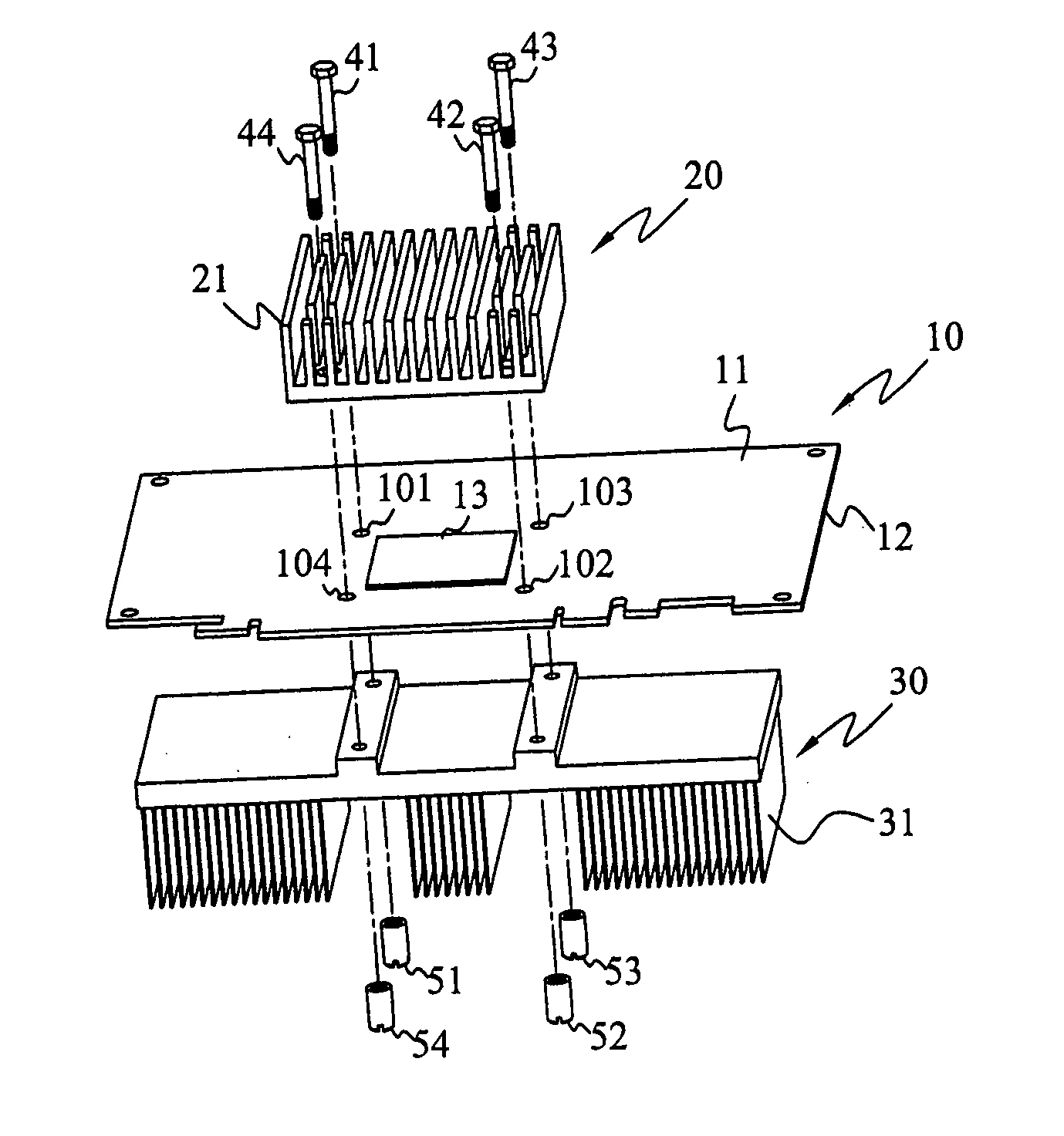
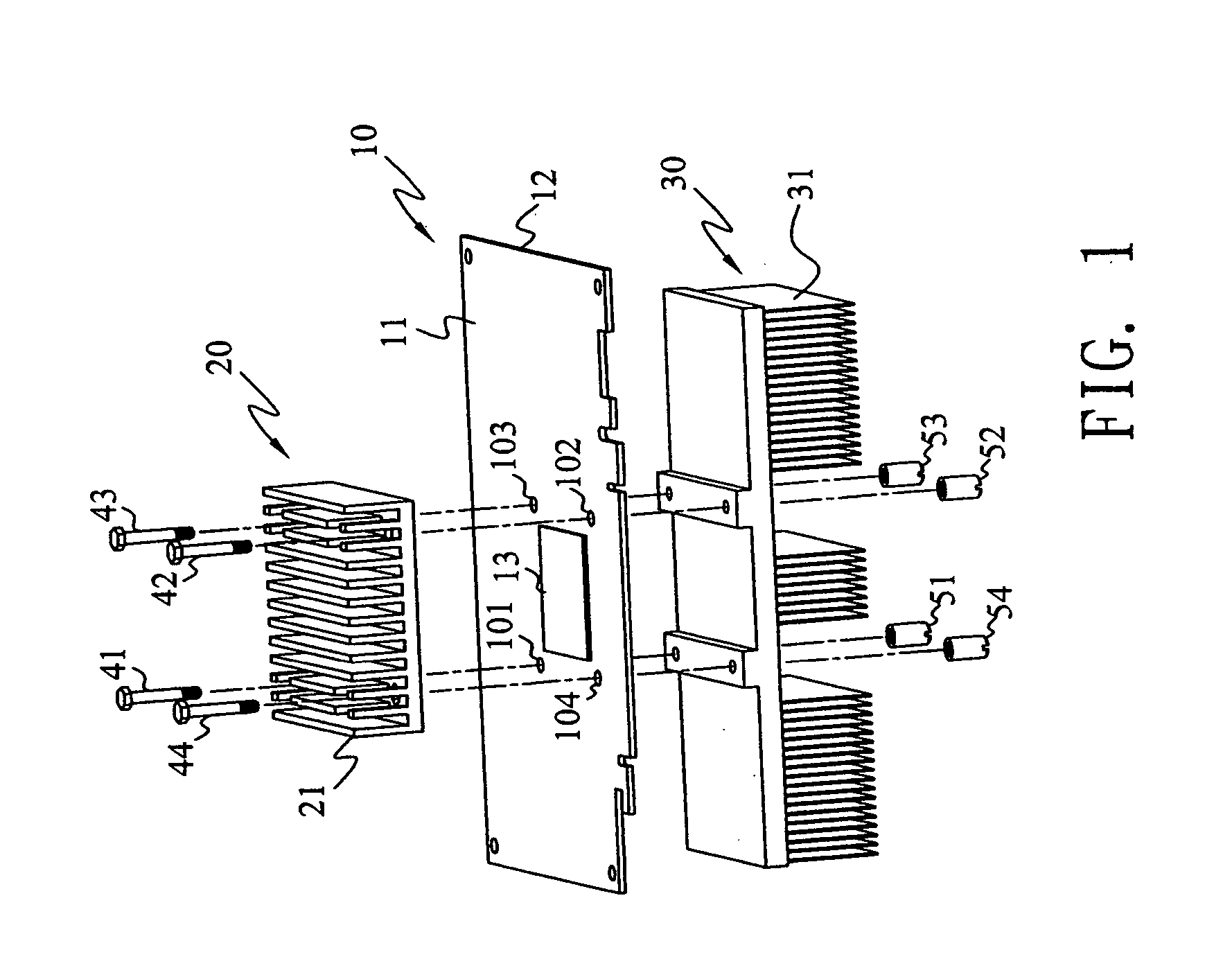
[0020] The principle of the design and implementation of the circuit board having heat dissipation through holes lies in placing the heat conduction elements directly in the through holes, so that the heat generated by the chips on the circuit board may be transferred from a heat dissipater to an auxiliary heat dissipater with the shortest possible distance. Usually, the heat conduction element is realized as a heat pipe made of copper or aluminum etc having high heat conduction coefficient, and the example of which will be described in detail in the following two preferred embodiments.

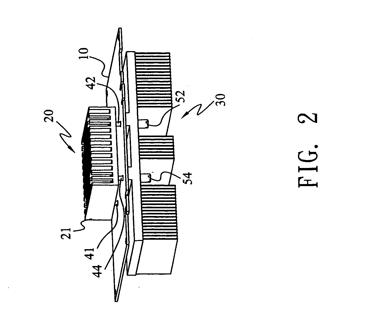
[0021] Firstly, refer to FIGS. 1 & 2. FIG. 1 is an exploded view of the circuit board having heat dissipation through holes according to the first embodiment of the invention. FIG. 2 is an assem...


PUM


Abstract

A circuit board having heat dissipation through holes, wherein a plurality of through holes are provided in the perimeter of the chip on the circuit board, and heat conduction elements are utilized to connect the heat dissipater and auxiliary heat dissipater provided on two sides of the circuit board. The heat conduction element may be the heat conduction column or heat pipe made of copper or aluminum, and is used to connect the heat dissipater and auxiliary heat dissipater with the shortest distance, thus achieving the speedy transfer of heat generated by the chips and raising the heat dissipation efficiency significantly.

Description

BACKGROUND [0001] 1. Field of Invention [0002] The invention relates a circuit board used for electronic device, and in particular to a circuit board having heat dissipation through holes. [0003] 2. Related Art [0004] Nowadays, circuit boards having major electronic components disposed thereon are widely utilized in various electronic devices. For example, the personal computer has various essential chips of central processor unit (CPU), South Bridge, North Bridge provided on its main board. Heat dissipaters are provided in the conventional computer to prevent overheating caused by the high operation speed of CPU. The heat dissipater is made of metal of high heat conductivity and having a plurality of heat sink fins, with its bottom directly in touch with CPU. Heat is absorbed through conduction and then dissipated by means of heat sink fins through convection. In order to raise the efficiency of heat convection and transfer, fans are installed on the heat dissipater to enhance heat...

Claims


Application Information

Patent Timeline
Patent Type & Authority Applications(United States)
IPC IPC(8): H05K7/20
CPCH01L23/3677H01L23/4006H01L23/427H01L2023/4056H01L2023/4062H01L2924/0002H01L2023/4087H01L2924/00
Inventor CHANG, CHIEN-LUNGHUANG, KUO-HSUN
Owner ASUSTEK COMPUTER INC
Why Eureka
Try Eureka