
Method for recovering from errors in flash memory

a flash memory and error recovery technology, applied in the field of flash memory data reading, can solve the problems of low data retention time quality specification of mbc cells, lower reliability of mbc than sbc, and low performance of mb

Active Publication Date: 2007-04-26
WESTERN DIGITAL ISRAEL LTD
View PDF9 Cites 401 Cited by
  • Summary
  • Abstract
  • Description
  • Claims
  • Application Information

AI Technical Summary

Benefits of technology

[0021] Some or all of the aforementioned needs, and other nee

Problems solved by technology

However, there may also some drawbacks to using MBC flash—the average read and write times of MBC memories are longer than of SBC memories, resulting in lower performance.
Also, the reliability of MBC is lower than SBC.
Thus, a disturbance in the threshold voltage (e.g. leaking of the stored charge causing a threshold voltage drift, interference from operations on neighboring cells, etc.) that may have gone unnoticed in SBC because of the large gap between the two states, might cause an MBC cell to move from one state to another, resulting in an erroneous bit.
The end result is a lower quality specification of MBC cells in terms of data retention time or the endurance of the device to many write / erase cycles.
Error Correction When Reading Data from Flash Cells
Even though it is common to employ Error Correction Codes (ECC) for correcting errors in data read from flash memory, the correction capability is typically limited to some fixed number of errors within the page of data being read, and eventually the accumulated number of errors might exceed the correction capability of the ECC mechanism.
It is noted that the aforementioned recovery method of Auclair suffers from a big disadvantage.
The situation is even worse in MBC NAND flash memory, where the writing of a page may take 800 microseconds while the reading of a page may take 30 microseconds.
This fact means that employing the method of Auclair for recovering a page of data may be a very slow operation.
For real-time software applications, this might be unacceptable.
Even if the writing stage of Auclair is delayed to a later time, so that the software application receives the data as soon as it is available and without waiting for the recovery process to complete, there is still a degradation in the throughput of the storage system due to the extra writing operation.

Method used


Image

  • Method for recovering from errors in flash memory
  • Method for recovering from errors in flash memory
  • Method for recovering from errors in flash memory

Examples


Embodiment Construction

[0058] The present invention will now be described in terms of specific, example embodiments. It is to be understood that the invention is not limited to the example embodiments disclosed. It should also be understood that not every feature of the presently disclosed method, device and computer-readable code for recovering from errors in flash memory is necessary to implement the invention as claimed in any particular one of the appended claims. Various elements and features of devices are described to fully enable the invention. It should also be understood that throughout this disclosure, where a process or method is shown or described, the steps of the method may be performed in any order or simultaneously, unless it is clear from the context that one step depends on another being performed first.

Flash Memory Device of FIG. 3

[0059]FIG. 3 provides a block diagram of a flash memory device 50 in accordance with exemplary embodiments of the present invention. The flash memory devic...


PUM


Abstract

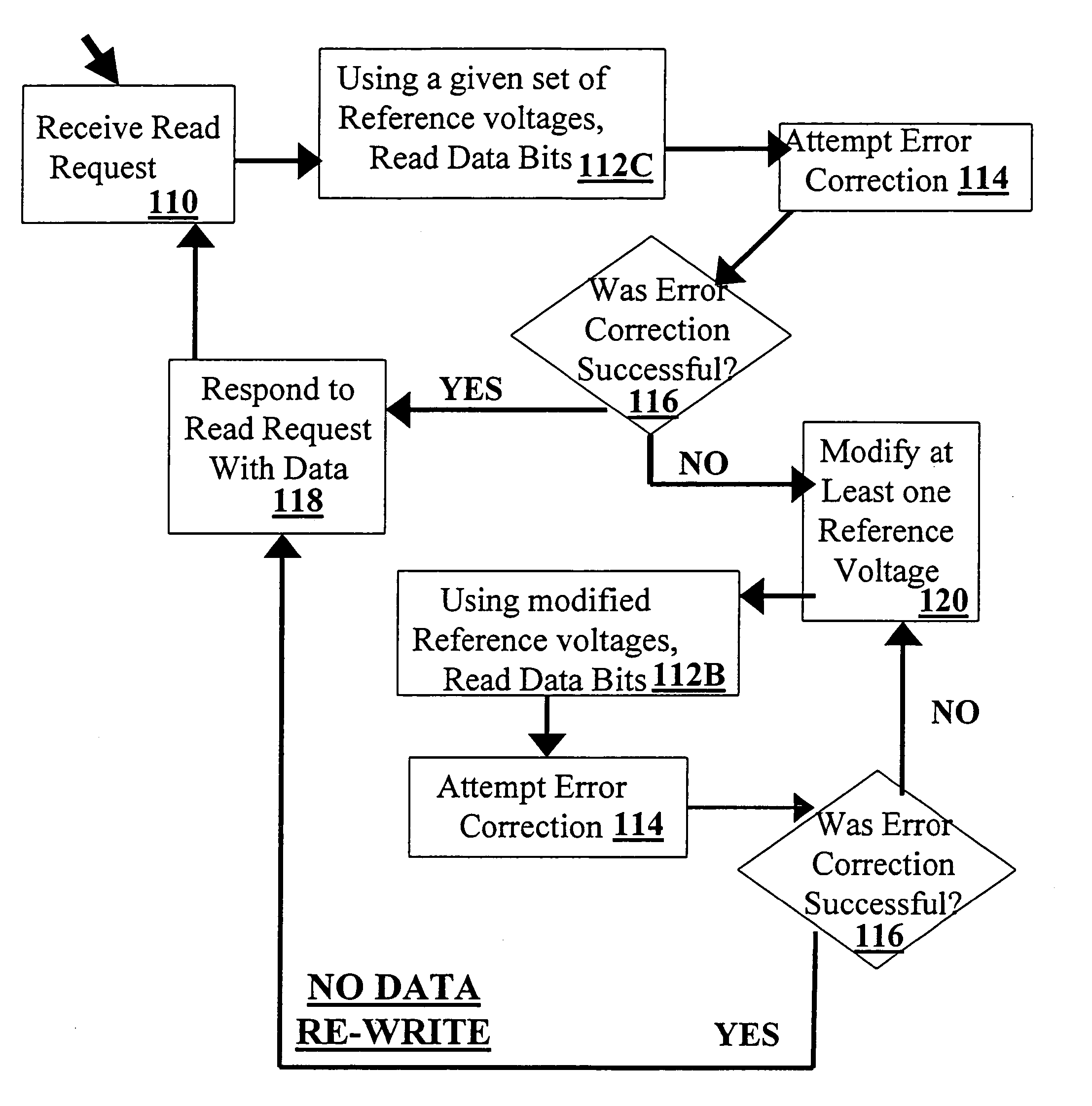
Methods, devices and computer readable code for reading data from one or more flash memory cells, and for recovering from read errors are disclosed. In some embodiments, in the event of an error correction failure by an error detection and correction module, the flash memory cells are re-read at least once using one or more modified reference voltages, for example, until a successful error correction may be carried out. In some embodiments, after successful error correction a subsequent read request is handled without re-writing data (for example, reliable values of the read data) to the flash memory cells in the interim. In some embodiments, reference voltages associated with a reading where errors are corrected may be stored in memory, and retrieved when responding to a subsequent read request. In some embodiments, the modified reference voltages are predetermined reference voltages. Alternatively or additionally, these modified reference voltages may be determined as needed, for example, using randomly generated values or in accordance with information provided by the error detection and correction module. Methods, devices and computer readable code for reading data for situations where there is no error correction failure are also provided.

Description

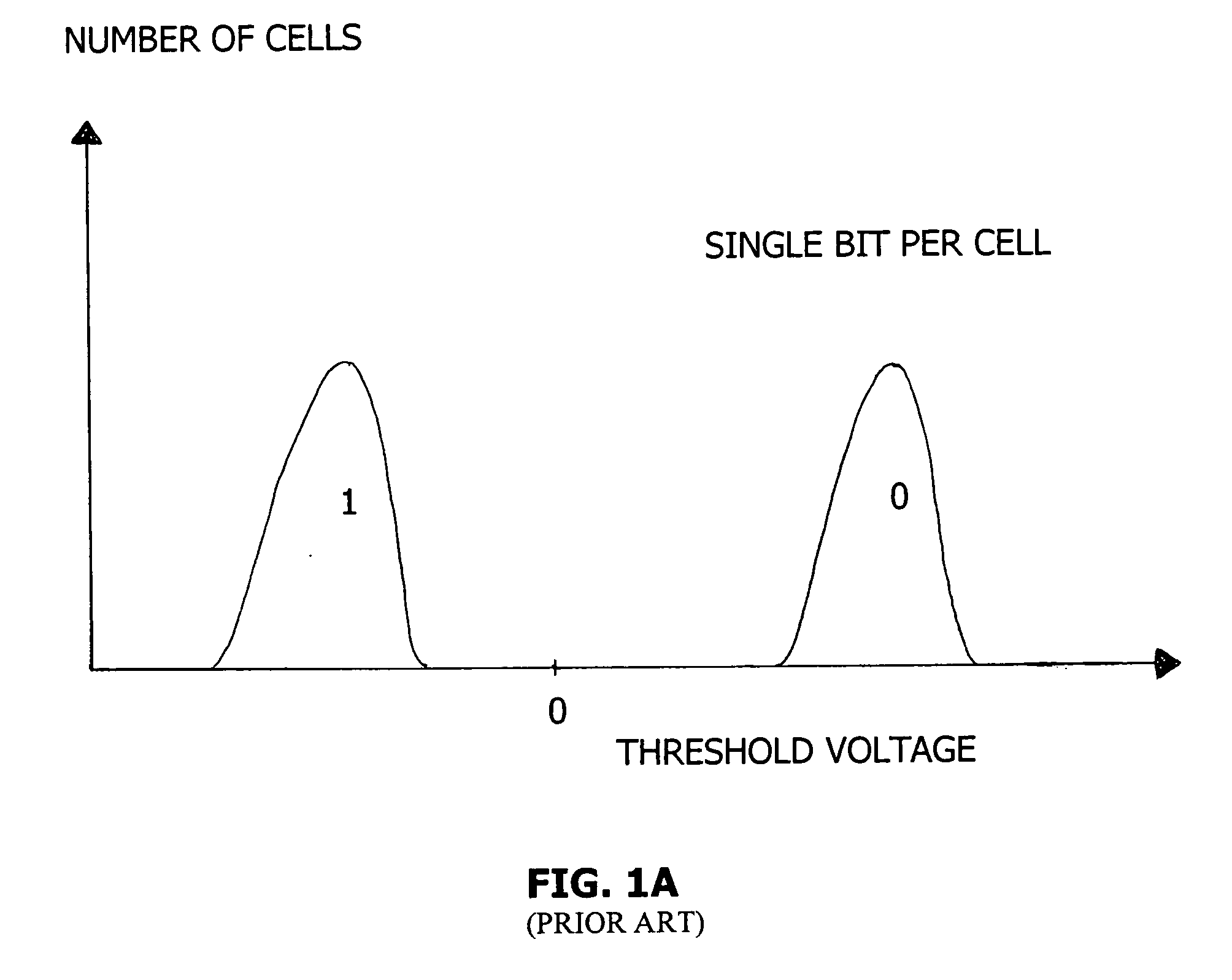
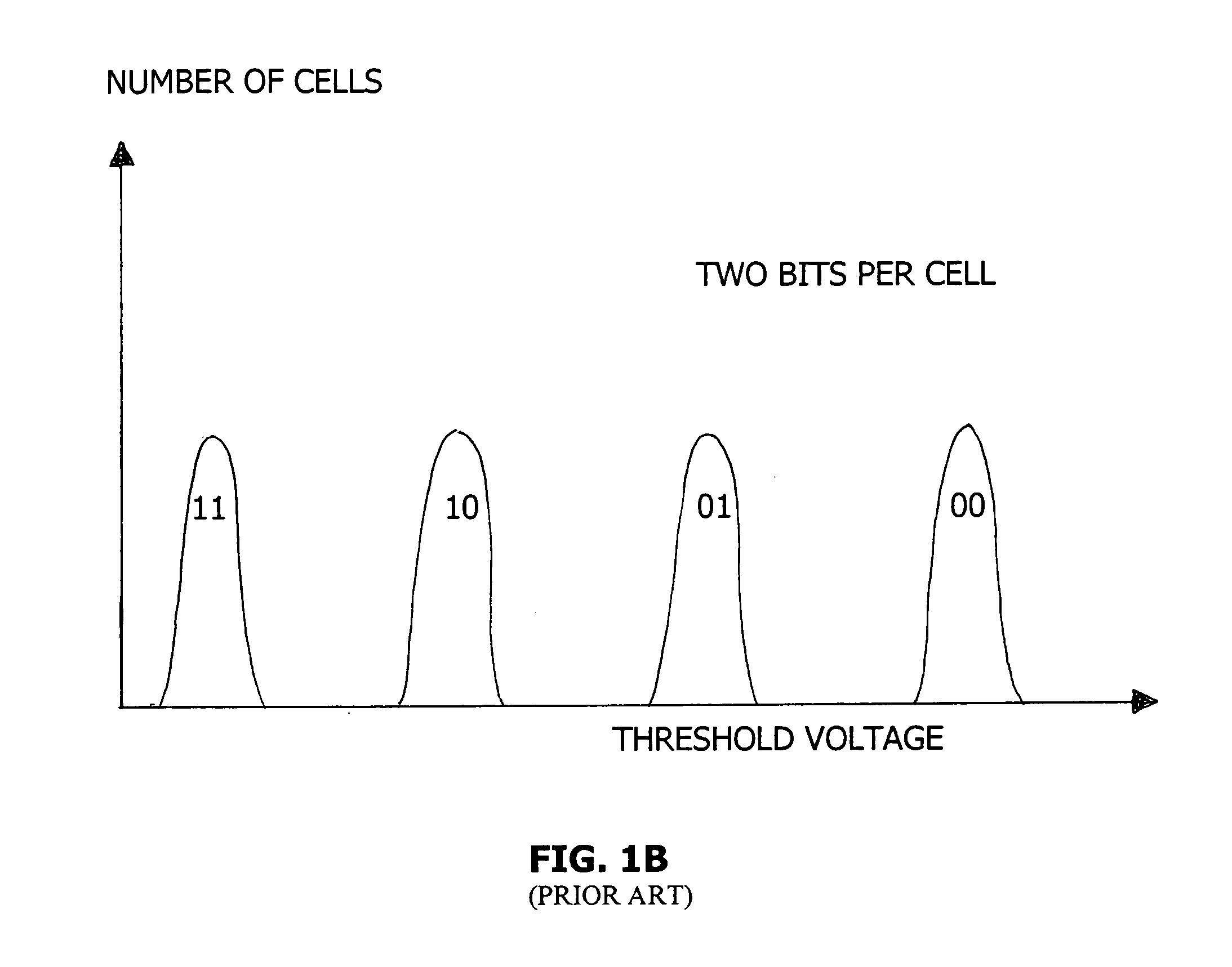
CROSS-REFERENCE TO RELATED APPLICATIONS [0001] This patent application claims the benefit of U.S. Provisional Patent Application No. 60 / 729,608, filed Oct. 25, 2005 by the present inventors.FIELD OF THE INVENTION [0002] The present invention relates to reading of data from flash memory in systems where reading errors may occur. BACKGROUND Single Bit and Multi-Bit Flash Memory Cells [0003] Flash memory devices have been known for many years. Typically, each memory cell within a flash memory device stores one bit of information. The traditional way to store a bit in a flash memory cell has been by supporting two states of the memory cell. One state represents a logical “0” and the other state represents a logical “1”. [0004] In a flash memory cell, the two states are implemented by having a floating gate situated above the cell's channel (the area connecting the source and drain elements of the cell's transistor), and having two valid states for the amount of charge stored within the...

Claims


Application Information

Patent Timeline
IPC IPC(8): G11C16/06
CPCG06F11/1068G06F11/1072G11C11/5642G11C16/28G06F11/07G06F11/10G11C16/06
Inventor LASSER, MENAHEMMURIN, MARK
Owner WESTERN DIGITAL ISRAEL LTD
Learn More