
Reference clock recovery circuit and data receiving apparatus

a data receiving apparatus and reference clock technology, applied in data switching networks, multiplex communication, selective content distribution, etc., can solve the problems of overflow or underflow of transfer data, increase the size of the apparatus, and more apparent, so as to prevent the loss of audio data and buffer the effect of underflow

Inactive Publication Date: 2007-04-26
NEC ELECTRONICS CORP
View PDF3 Cites 25 Cited by
  • Summary
  • Abstract
  • Description
  • Claims
  • Application Information

AI Technical Summary

Benefits of technology

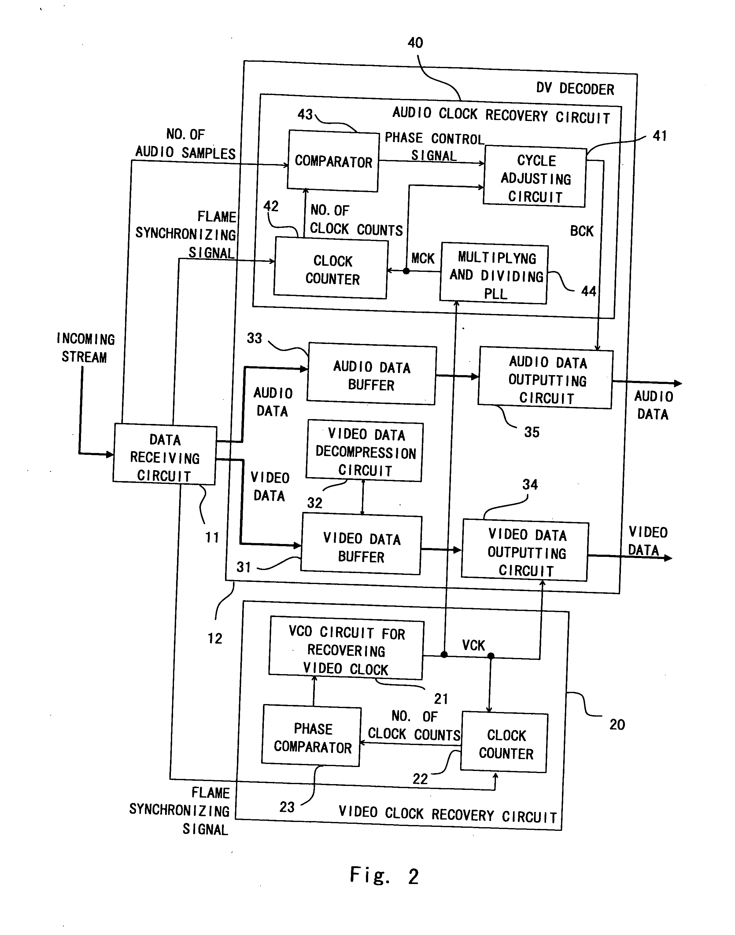
[0016] In the present invention a video clock is multiplied and divided to generate a clock for recovering an audio clock. Then clocks for recovering audio clock are counted so as to adjust a cycle of the audio clock according to the result of the count and the number of audio samples included in an incoming stream. This enables to match the number of audio clocks in one frame with the number of audio samples. Accordingly without using VCO, the receiving side is able to recover an audio clock capable of preventing losing audio data and buffer underflow as well as seamlessly transmitting audio data.

Problems solved by technology

Therefore in case a simple PLL (Phase Locked Loop) multiply circuit is used, there could be a difference generated between the number of audio samples, thereby causing an overflow or underflow of a transfer data.
Accordingly area for the analog circuits is required, thereby increasing the size of an apparatus.
This problem also applies to the technique disclosed in Miyamoto.
However this problem can be more apparent for DV because two clock recovery circuits are required for audio and video.

Method used


Image

  • Reference clock recovery circuit and data receiving apparatus
  • Reference clock recovery circuit and data receiving apparatus
  • Reference clock recovery circuit and data receiving apparatus

Examples


Embodiment Construction

[0027] The invention will be now described herein with reference to illustrative embodiments. Those skilled in the art will recognize that many alternative embodiments can be accomplished using the teachings of the present invention and that the invention is not limited to the embodiments illustrated for explanatory purposes.

[0028] This embodiment is a DV decoder having a clock recovery circuit capable of recovering an audio clock only by a video clock and seamlessly transmitting audio data in a DV format data transmission, whereby the present invention is applied thereto.

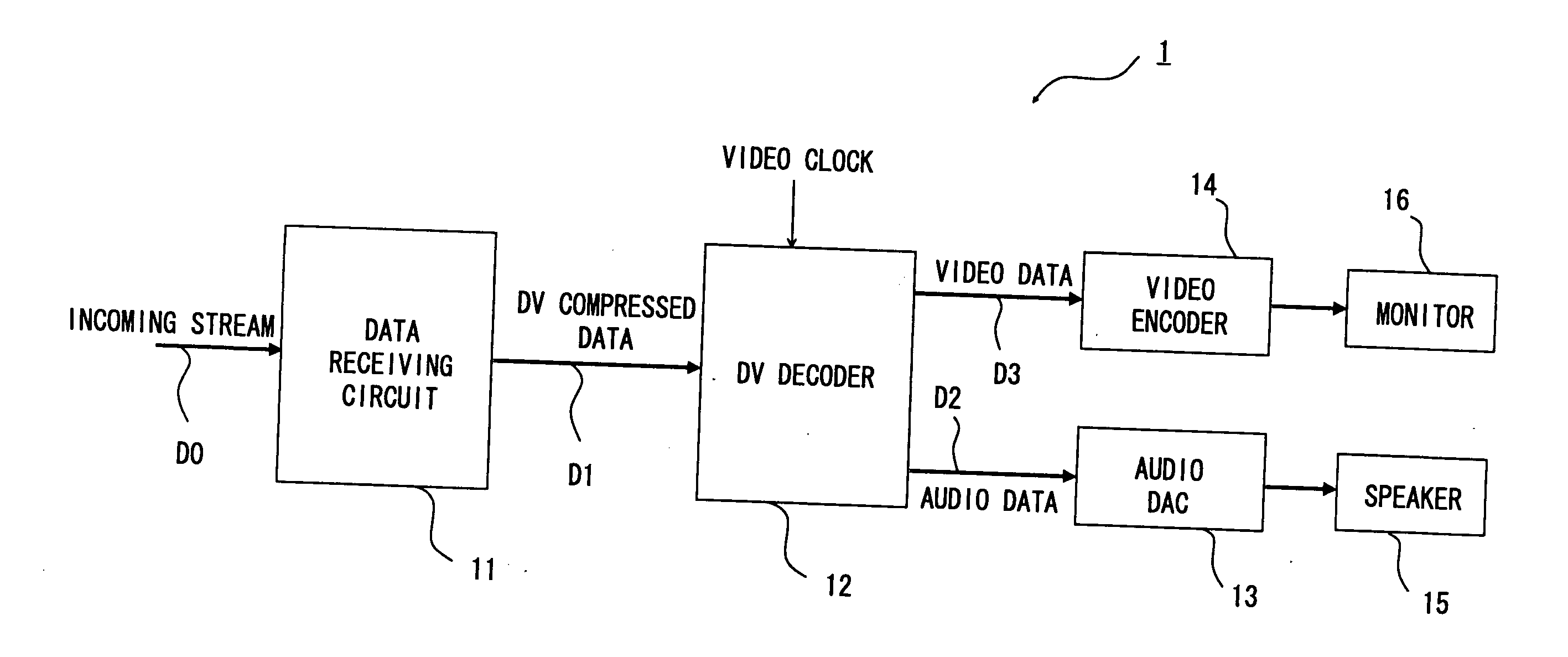
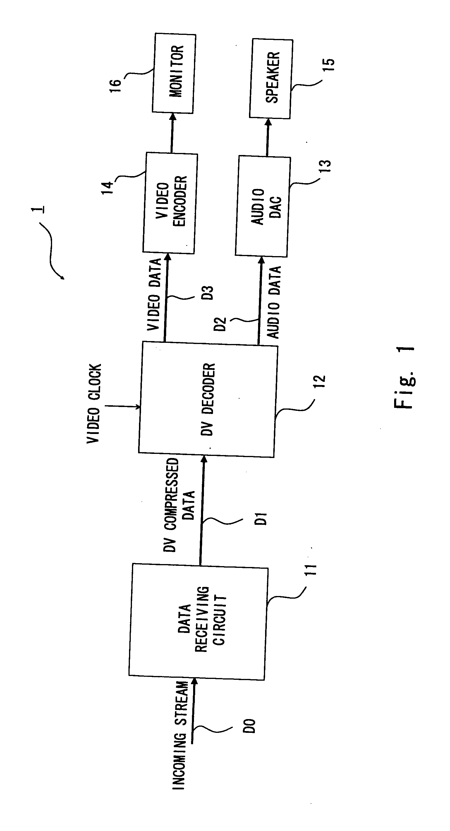
[0029]FIG. 1 is a block diagram showing a receiving system with a DV decoder having a clock recovery circuit of this embodiment. As shown in FIG. 1, a receiving system 1 includes a data receiving circuit 11 for receiving a incoming stream DO including DV packets and a DV decoder for receiving a DV compressed data D1 from the data receiving circuit 11.

[0030] A video clock is supplied to the DV decoder 12. Then an...


PUM


Abstract

An audio recovery circuit is supplied with a video clock VCK that synchronizes with a video clock of a sending side recovered according to a frame synchronizing signal generated based on an incoming stream. The audio recovery circuit includes a PLL circuit for multiplying and dividing VCK to generate an audio master clock MCK, a counting circuit for counting the number of MCKs in one frame, and a cycle adjusting circuit for generating an audio bit clock BCK from a specified number of MCKs. The cycle adjusting circuit adjusts a cycle of BCK in a unit of MCK so that the number of clocks corresponds with the number of samples, according to the number of audio samples to be sent and the number of current MCK.

Description

BACKGROUND OF THE INVENTION [0001] 1. Field of the Invention [0002] The present invention relates to a reference clock recovery circuit for recovering a reference clock of audio and / or video data included in an incoming stream, for example, and a data receiving apparatus having such reference clock recovery circuit therein. [0003] 2. Description of Related Art [0004] Generally a receiving apparatus for receiving video or audio data needs to recover a video or audio clock to process the data. A receiving apparatus for recovering an audio reference clock from a video reference clock is disclosed in Japanese Unexamined Patent Application Publication No. 2004-80557 (Miyamoto), for example. [0005] In the receiving apparatus disclosed in Miyamoto, a frequency of the audio reference clock may differ depending on an audio signal to be transmitted. However this receiving apparatus is to recover an audio clock using a common VCO (Voltage Controlled Oscillator) even in such a case. [0006] Stre...

Claims


Application Information

Patent Timeline
Patent Type & Authority Applications(United States)
IPC IPC(8): H04J3/06
CPCH04N21/2368H04N21/4305H04N21/4341
Inventor YONEZAWA, TAKESHIOOSHIMA, IZUMI
Owner NEC ELECTRONICS CORP
Learn More