WAVELENGTH LOCKING AND POWER CONTROL SYSTEMS FOR MULTI-CHANNEL PHOTONIC INTEGRATED CIRCUITS (PICs)
What is Al technical title?
Al technical title is built by PatSnap Al team. It summarizes the technical point description of the patent document.
a technology of photonic integrated circuits and power control systems, which is applied in the direction of instruments, semiconductor lasers, optical elements, etc., to achieve the effect of convenient implementation, convenient derivation of the average optical channel power, and orthogonal orthogonality
Inactive Publication Date: 2007-04-26
INFINERA CORP
View PDF22 Cites 31 Cited by
Summary
Abstract
Description
Claims
Application Information
AI Technical Summary
This helps you quickly interpret patents by identifying the three key elements:
Problems solved by technology
Method used
Benefits of technology
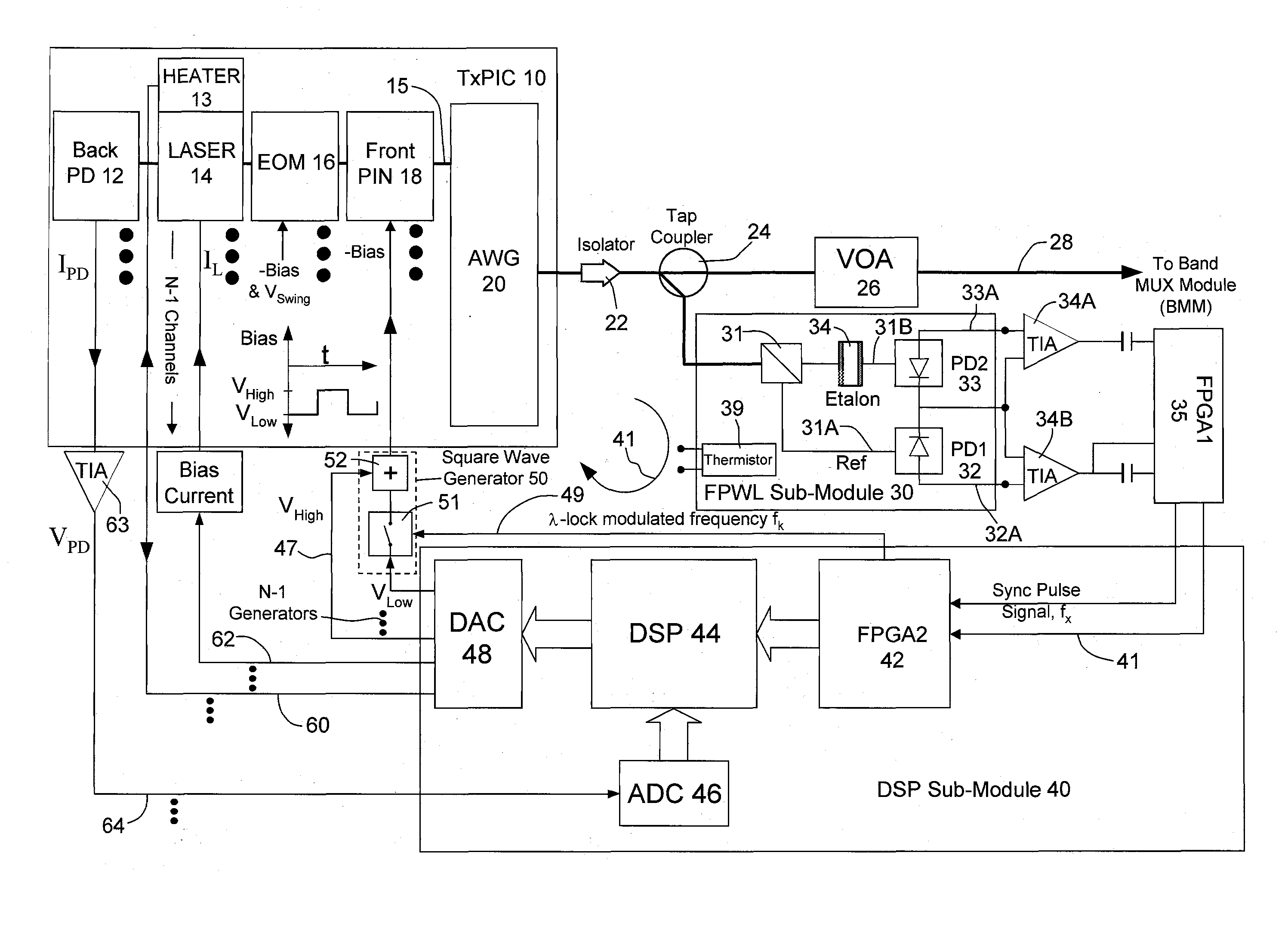
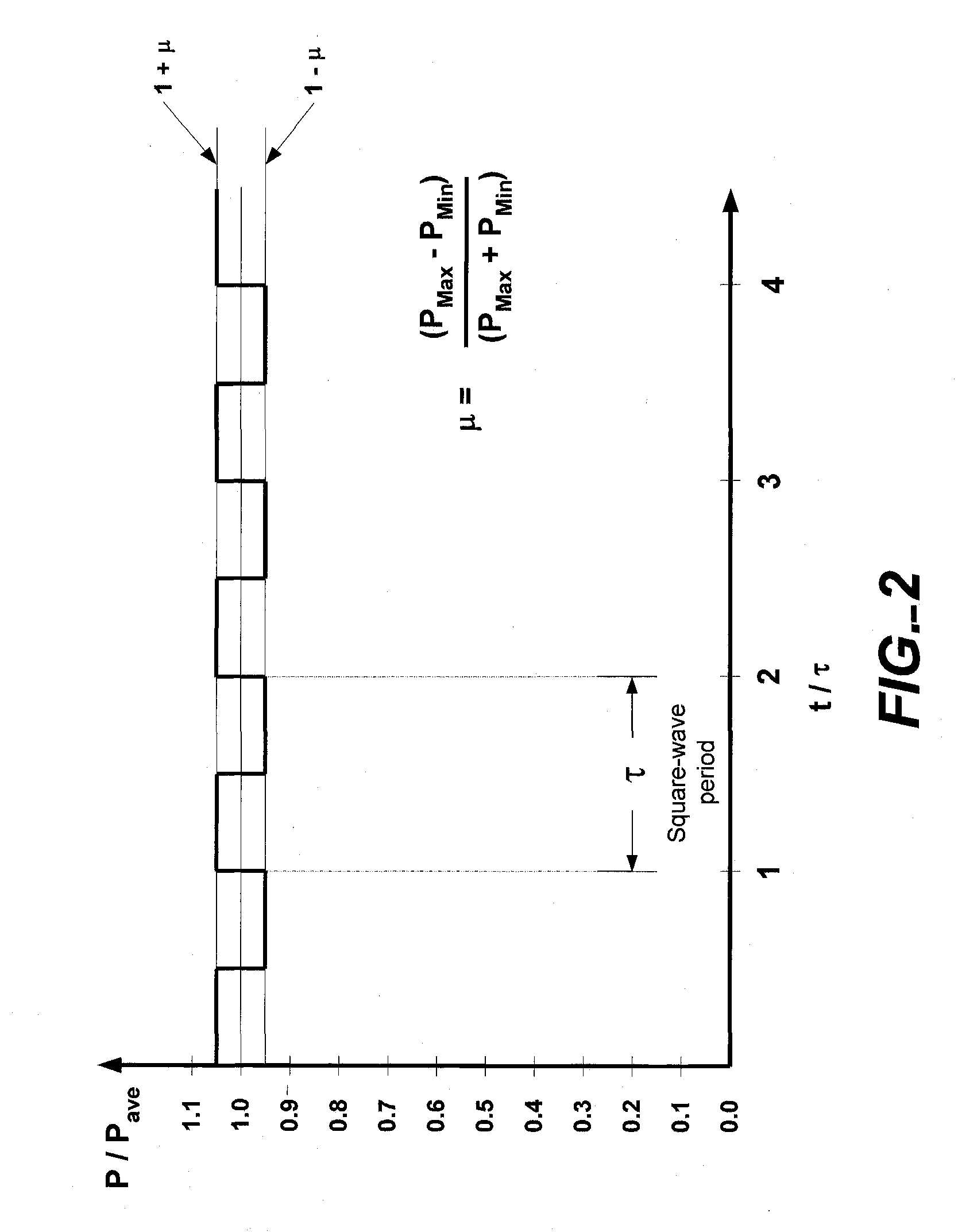
[0012] To label the individual channels within an optical multiplexed signal, carefully selected intensity modulation waveform schemes can be used. One such labeling scheme uses square waves whose fundamental frequencies and phase relationships are chosen to produce approximate mathematical orthogonality of the product of any pair of different square waves over a particular integration time interval. In this scheme, each channel is intensity modulated by applying the appropriate square wave “tone” to the bias input of the channel's front PIN. The fundamental frequency of the square wave tone is unique to its assigned channel in the multiplexed signal, and the depth of optical modulation is made to be known and constant based on the calibrated transfer function (transmittance versus bias) of the channel's front PIN. All channels in the multiplexed signal of interest are intensity modulated in parallel, with waveforms synchronized to maintain optimal orthogonality. Detection of the attributes of an individual channel in the multiplexed signal involves demodulation of the composite detected signal using the channel's assigned label. Consider the output of a photodetector that has as its input a tapped portion of the optical multiplexed signal. The photocurrent will contain, among other things, AC signals associated with the constant optical modulation index intensity modulation labels for each channel in the multiplexed signal. The composite photocurrent signal can be converted to a voltage and densely sampled by an analog to digital converter to enable subsequent digital signal processing. To extract the information associated with a particular channel, the product of the sampled composite signal and the channel's selected and synchronized square wave is created and integrated over a period chosen to provide approximate orthogonality among different square waves labeling channels in the multiplexed signal. In this way, the portion of the composite signal that corresponds to the square wave labeling the individual channel of interest is extracted by digital signal processing, Owing to the approximate mathematical orthogonality of the selected square waves, the output of the integration process is a single number primarily determined by the strength of the tone labeling or tagging of a channel under test. Cross-correlation terms from all the other channels can be made sufficiently
Problems solved by technology
While advantageous for reliability and reduction of cost, this integrated multiplexing function poses challenges for control of individual optical wavelengths and channel ave
Method used
Image
Click on the blue label to locate the original text in one second.
Reading with bidirectional positioning of images and text.
Examples
Embodiment Construction
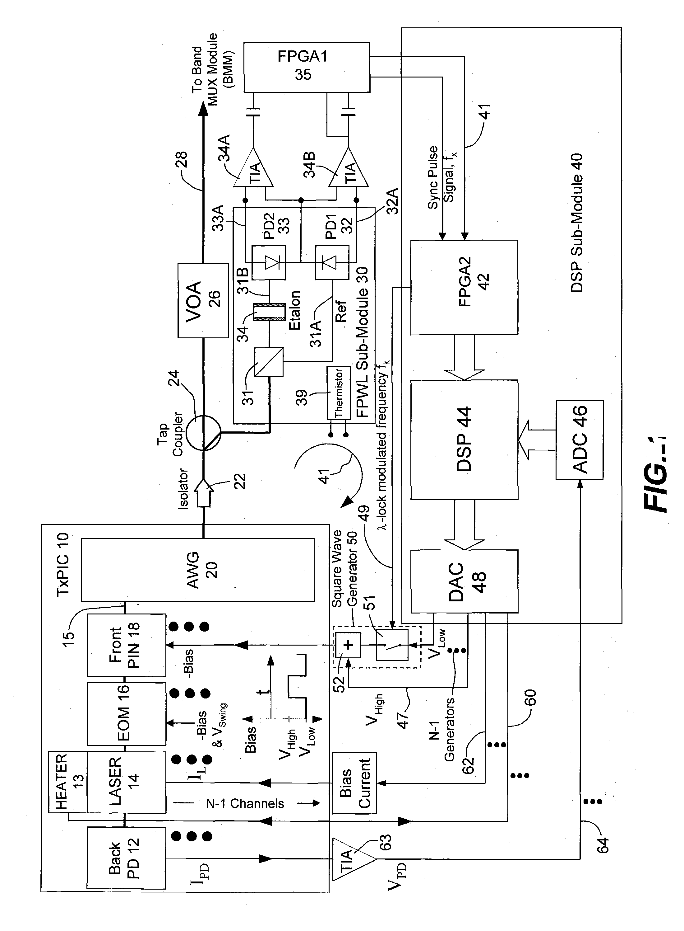
[0028] In FIG. 1, transmitter photonic integrated circuit (TXPIC) 10 may be a semiconductor circuit chip and contains a plurality of N integrated signal channels 15 where each channel comprises, in a serial train of elements along each channel, a back photodetector (PD) 12, a semiconductor laser 14 (DFB laser or DBR laser), electro-optic modulator (EOM) 16 (shown here as an electro-absorption modulator or EAM but can also be, for example, a Mach-Zehnder modulator) and a front PIN 18. We refer to a signal channel combination of laser 14 and electro-optical modulator 16 as a channel modulated source. Another type of modulated source that may be employed in channels 15 of TxPIC 10 is a directly modulated laser which, of course, removes the requirement for an external modulator 16 in each channel 11. In TxPIC 10, there are, then, N signal channels 15 with N lasers 14 that have different optical carrier frequencies or emission wavelengths that operate along uniform frequency grid spacing...
PUM
Abstract
A transmissive active channel element is provided in each signal channel of a monolithic multi-channel TxPIC where each channel also includes a modulated source. The active channel element functions both as a power control element for both monitoring and regulating the output channel signal level of each signal channel and as a modulator for channel wavelength tagging or labeling to provide for wavelength locking the modulated sources. The power regulating function is also employed to control the channel signal power outputs of each channel to be uniform across the channel signal array. All of these functions are carried out by a feedback loop utilizing digital signal processing.
Description
REFERENCE TO RELATED APPLICATION [0001] This application claims priority to provisional application, Ser. No. 60 / 695,382, filed Jun. 30, 2005, and is also a continuation-in-part of nonprovisional patent applications, Ser. No. 10 / 267,330, filed Oct. 8, 2002 and entitled, TRANSMITTER PHOTONIC INTEGRATED CIRCUIT (TXPIC) CHIP ARCHITECTURES AND DRIVE SYSTEMS AND WAVELENGTH STABILIZATION FOR TxPICs, which claims priority to provisional application Ser. No. 60 / 370,345, filed Apr. 5, 2002; and Ser. No. 10 / 267,331, filed Oct. 8, 2002 and entitled, TRANSMITTER PHOTONIC INTEGRATED CIRCUITS (TXPIC) AND OPTICAL TRANSPORT NETWORKS EMPLOYING TxPICs, which claims priority to provisional application, Ser. No. 60 / 328,207, filed Oct. 9, 2001, all of which applications are incorporated herein by their reference in their entirety.BACKGROUND OF THE INVENTION [0002] This invention relates to wavelength locking and output power control systems relative to multiple WDM signal channels and more particularly ...
Claims
Application Information
Patent Timeline
Application Date:The date an application was filed.
Publication Date:The date a patent or application was officially published.
First Publication Date:The earliest publication date of a patent with the same application number.
Issue Date:Publication date of the patent grant document.
PCT Entry Date:The Entry date of PCT National Phase.
Estimated Expiry Date:The statutory expiry date of a patent right according to the Patent Law, and it is the longest term of protection that the patent right can achieve without the termination of the patent right due to other reasons(Term extension factor has been taken into account ).
Invalid Date:Actual expiry date is based on effective date or publication date of legal transaction data of invalid patent.