The valves of the prior art help considerably, of course, but a satisfactory solution has not yet been achieved with the valves of the prior art.
The function of a construction of this type is somewhat doubtful, however, because in
actual use, the housing is carrying a flow of a watery solution (liquor).
The sliding characteristics between
silicon and the rotor are thereby unfavorably altered.
The elastic tension is insufficient to guarantee a friction-tight protection against twisting.
Since it is practically impossible for a modern
human being to avoid contact with such things, proposed solutions of this type are simply impractical.
This principle has in fact shown itself to be susceptible to failure in
actual practice.
Although unintentional rotation is prevented, the intended adjustment is frequently unsuccessful.
This problem can be traced to the difficulty of reliably determining the exact position of the valve, because in
actual use, friction forces that are difficult to calculate interfere with or even totally prevent the movement of the sliding magnets inside the valve.
An additional
disadvantage is that because the
layers of
skin at these points can be rather thick, the two sliding magnets must be pulled far apart, whereby the forces resulting from the externally applied
magnetic field become exponentially smaller as the distance increases, and in any case are then no longer sufficient to pull the magnets apart.
Here, too, the extremely problematic technology of a 100% magnetic
brake in a hydrocephalus valve also becomes apparent.
This principle has never been found to be either practical or reliable.
In particular, the many small
moving parts contribute to a critical addition of disruptive friction forces, which cannot be controlled, for among other reasons on account of the small size of the valve and also as a result of the magnets used.
The pins can very easily tip out of alignment, and the friction in the threads that is applied externally with a long lever arm is almost impossible to overcome with the very weak
magnetic field derived from the small magnets.
The thread must also have some play to allow smooth movement, which in turn is disadvantageous to the accuracy of the adjustment.
The location of the valve is also problematic here, and an exact adjustment is practically impossible to achieve on account of the small size of the parts that have to be moved.
Because of the use of a
silicone membrane, the reproducible setting of the opening pressure is impossible, because the properties of the material vary incalculably.
For the reasons indicated above, this design has not yet reached a stage where it is ready for the market.
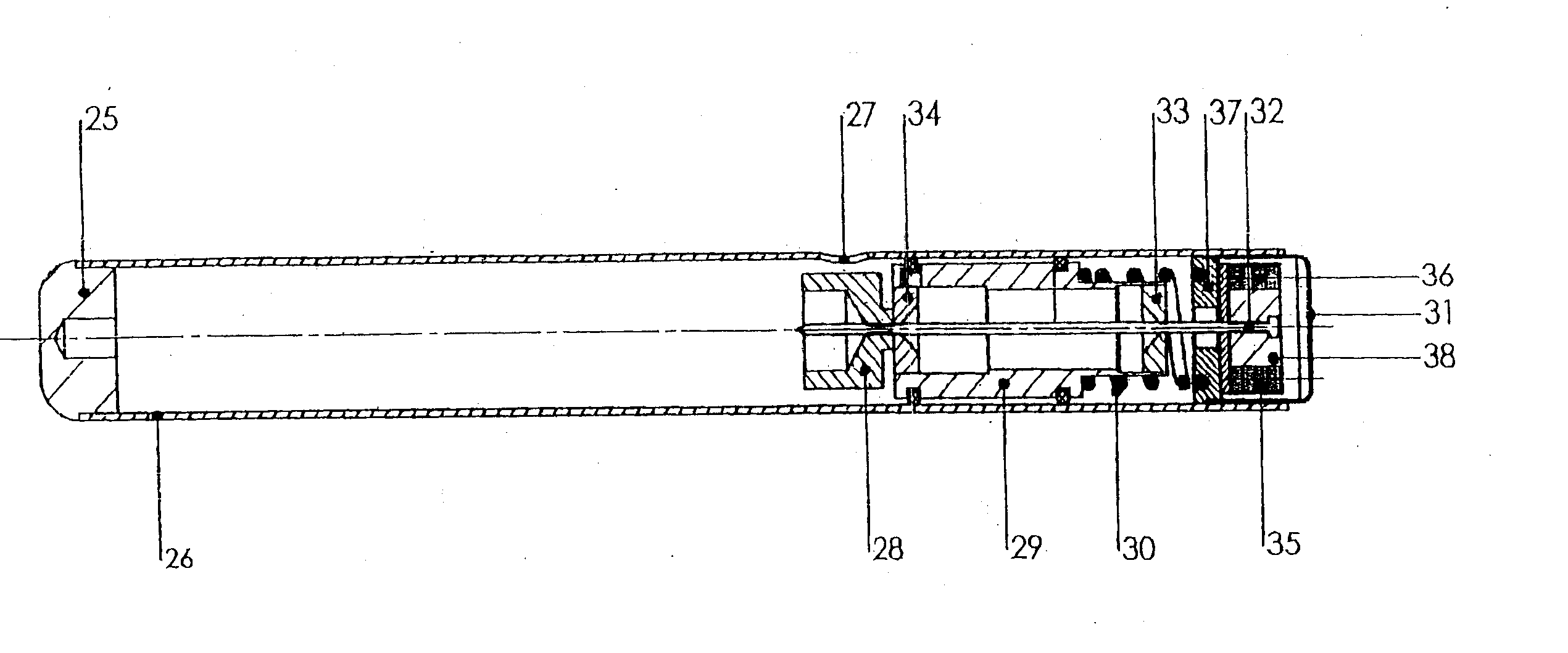
However, clinical use has made it clear that the pin can cause a critical jamming of the rotor.
The manufacturer was forced to withdraw this unreliable technology from the market and thereafter market the valve without the mechanism to prevent the unintentional adjustment.
The danger of the unintentional adjustment therefore remains present, in particular when the requirement for the ability to reliably adjust the valve is taken into consideration.
An additional
disadvantage of the
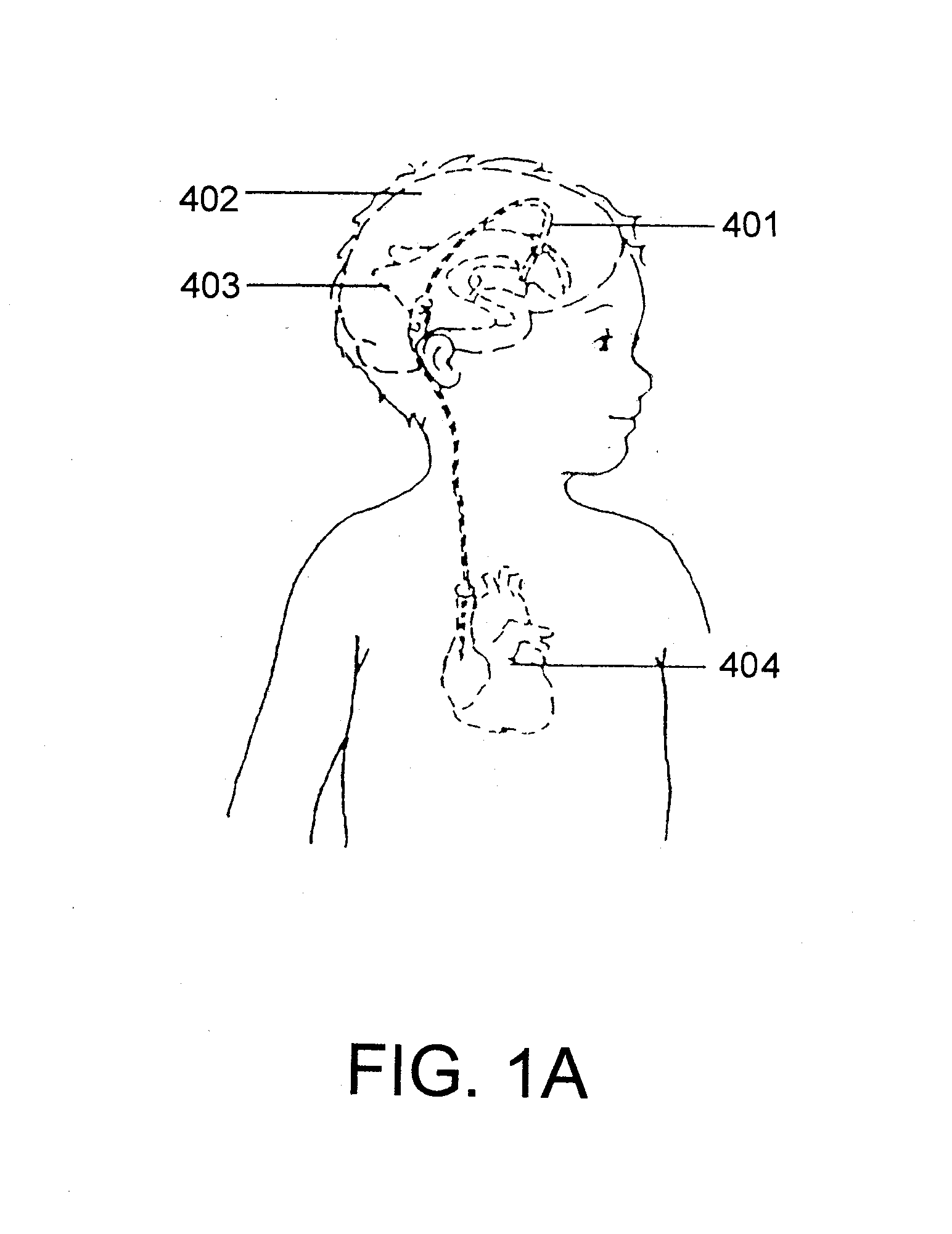
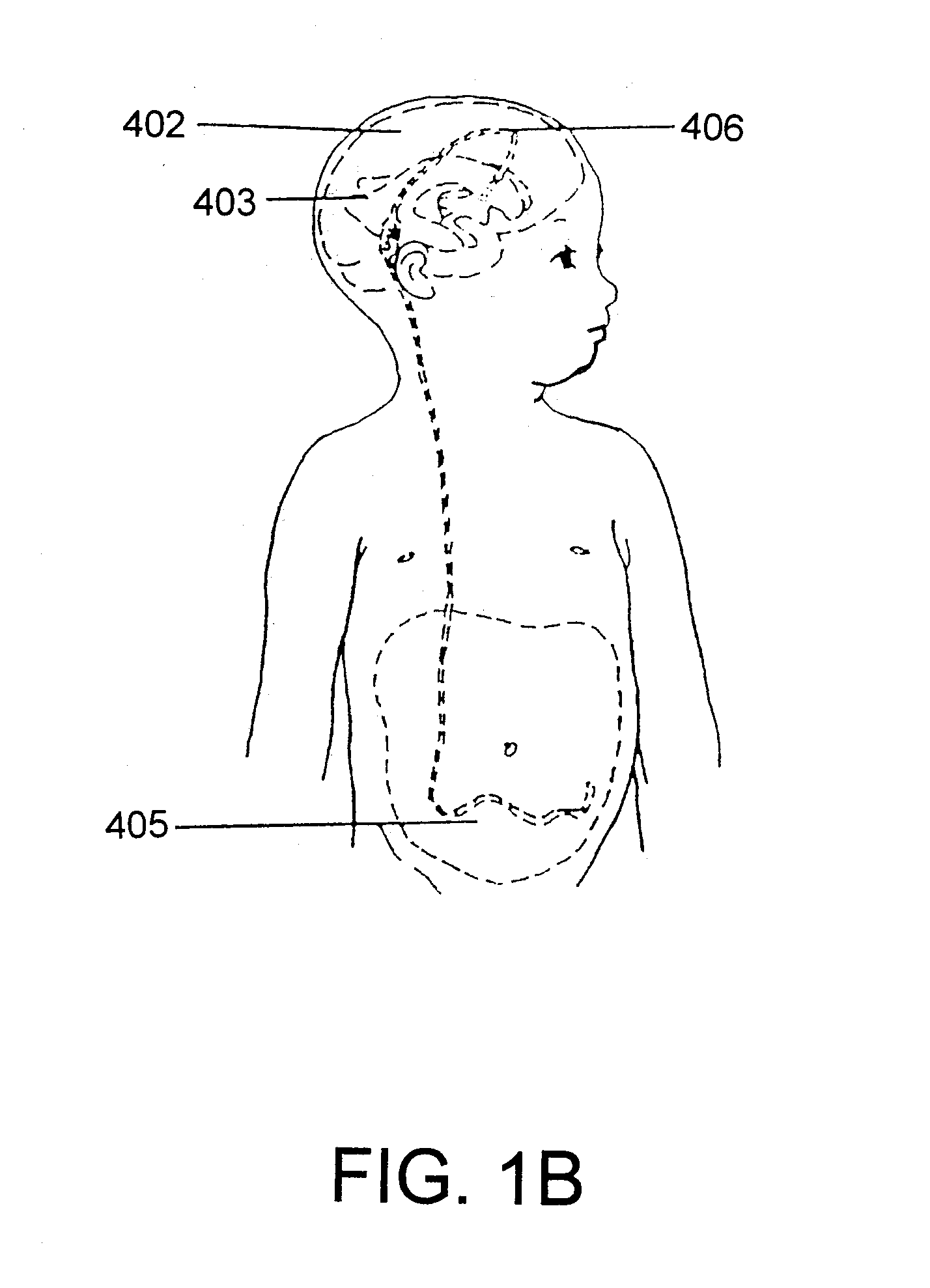
system of the prior art is that the adjustment must be effective both in the standing position as well as in the reclining position.
However, this is a characteristic that is frequently undesirable.
The consequence for the patient is a physiologically uncomfortable pressurization of the
ventricle of the brain immediately after standing up, which can lead to discomfort and dizziness as well as to serious complications such as subdural effusions and bleeding that must be treated by
surgery.
It is not possible to prevent such complications with the valves described above.
In this case, the adjustment travel that is converted into a variation of the spring load is particularly large.

