Pedicle fixation rod alignment system

a technology of fixation rod and pedicle, which is applied in the field of vertebral stabilization devices and methods, can solve the problems of difficult visualization of the alignment accuracy of the rod with the screw head, and achieve the effects of reducing the need for significant tissue dissection and retraction, reducing surgical time, and creating more lordosis

Inactive Publication Date: 2007-04-26
ZIMMER SPINE INC
View PDF40 Cites 135 Cited by
  • Summary
  • Abstract
  • Description
  • Claims
  • Application Information

AI Technical Summary

Benefits of technology

[0007] Once the modification of the rod is complete, i.e., bending and cutting to length, the tissue can be cut between the pedicle screws and dissected in a minimally invasive manner for placement of the rod followed by closing the incision after rod placement and securing. The rod may come in a series of varying radiuses, i.e., pre-bent, so the surgeon could simply place a pre-bent rod into the provisional saddles and change the rod with a different pre-bent rod as needed. The amount of pre-bending of the rod may be undersized with respect to the saddle trajectory to create more lordosis on the construct when the rod is fixed in place.
[0008] One advantage of the system of this invention is that the pedicle screws could be placed, and the rod modified, sized and bent using this device, after which a minimally invasive interconnecting incision is made to the pedicle screw heads so the rod can be placed and tightened. Alternatively, the modified rod may be inserted into the first incision and fed through all of the pedicle screw head saddles. Either of these insertion methods may potentially reduce the surgical time, as well as reduce necessity of significant tissue dissection and retraction during surgery.
[0009] Another advantage of this system is the increased visualization of the fit of the rod to the pedicle screw head saddles. Very often, this is instrumental in achieving the intended outcome. In traditional surgery, visualization of the actual fit of these components is difficult because of blood and tissue. In addition, elimination of the need to significantly retract tissue is a large benefit that could provide a quicker recovery time.

Problems solved by technology

Rod bending is performed once the screws are placed into vertebrae and, therefore, visualization of the accuracy of the alignment of the rod with the screw heads is difficult.

Method used


Image

  • Pedicle fixation rod alignment system
  • Pedicle fixation rod alignment system

Examples


Embodiment Construction

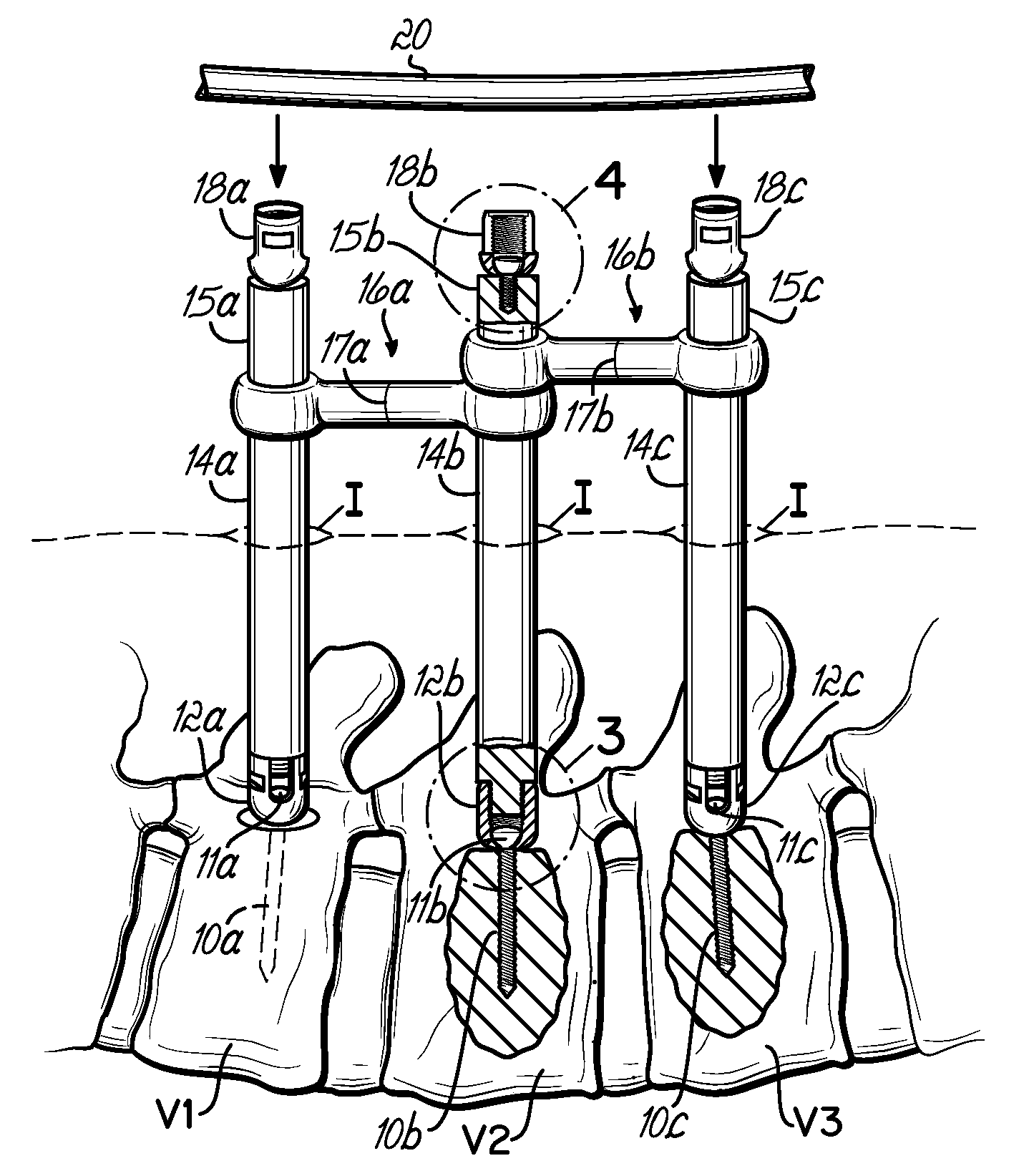
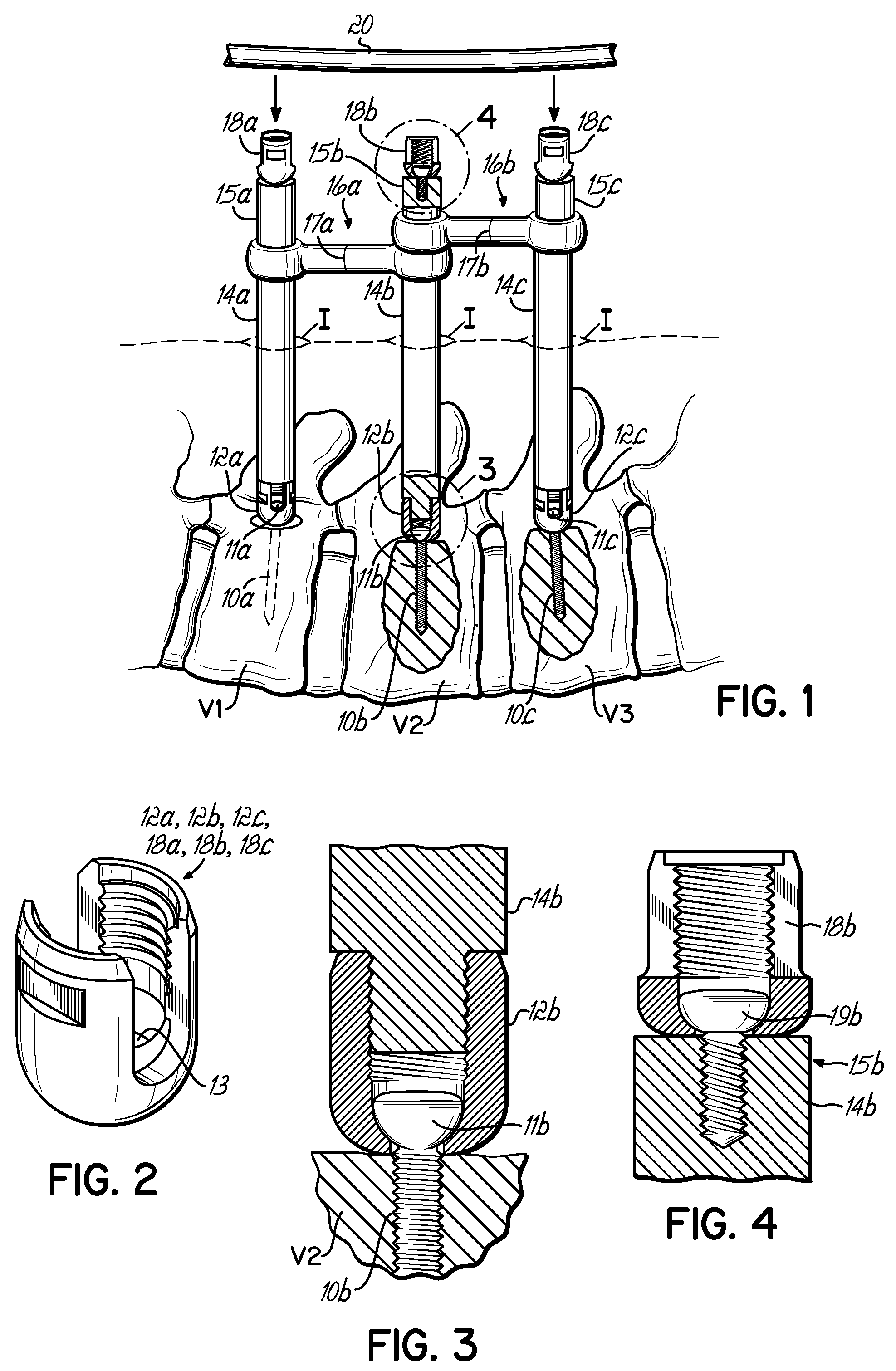
[0018] In general, the system of this invention provides a trial assembly for trialing a pedicle fixation rod exteriorly of a patient during surgery.

[0019] The present method and devices employ similar minimally invasive surgical methods and devices as described in U.S. patent application Ser. No. 11 / 228,958, entitled APPARATUS AND METHOD FOR MINIMALLY INVASIVE SPINE SURGERY, filed on Sep. 16, 2005, assigned to the assignee of this invention and the disclosure of which is expressly incorporated herein by reference.

[0020] Referring now to FIG. 1, a spinal fixation construct according to various embodiments of this invention includes a number of vertebral anchors in the form of pedicle screws 10a, 10b, 10c having pedicle screw heads 11a, 11b, 11c, respectively, positioned in vertebrae V1, V2, and V3 after a surgeon makes a plurality of small incisions I in the skin of the patient proximate vertebrae V1, V2, and V3. The pedicle screws 10a, 10b, 10c include pedicle screw head saddles ...


PUM


Abstract

A method and associated system of implanting a vertebral anchor such as a pedicle screw assembly includes the steps of implanting a number of pedicle screws into a series of vertebrae; attaching a number of provisional posts to respective pedicle screws, each provisional post including a provisional saddle; bending a rod to conform to a desired alignment of the provisional saddles; removing the provisional posts from the pedicle screw heads; and connecting the bent rod to the pedicle screw heads. Advantageously, the method allows external fitting and sizing of a fixation rod before it is implanted and secured to the vertebral anchors via a minimally invasive manner.

Description

[0001] This claims priority to U.S. Provisional Application Ser. No. 60 / 719,380, filed Sep. 22, 2005 and hereby incorporated by reference in its entirety.BACKGROUND [0002] This invention relates to a device and method for vertebral stabilization using pedicle anchors and fixation rods. [0003] Conventional vertebral stabilization surgery using pedicle screws and fixation rods requires a surgeon to prepare a long incision aligned with the vertebral column of a patient. Pedicle screws are then inserted into a number of vertebrae after which a fixation rod is located with respect to saddles attached to the pedicle screws. The fixation rod is then bent to match the orientation of the pedicle screw heads and / or the desired curvature of the spine. Visualization of the accuracy of the alignment of the rod and the screw heads may be difficult because of visual interference from tissue and blood, for example. Conventional surgical methods require a large midline incision and retraction of ski...

Claims


Application Information

Patent Timeline
Patent Type & Authority Applications(United States)
IPC IPC(8): A61F2/30
CPCA61B17/7032A61B17/7037A61B17/8863
Inventor HESTAD, HUGH D.EMSTAD, ERIK E.
Owner ZIMMER SPINE INC
Why Eureka
Try Eureka