Heat dissipation having a heat pipe

a heat pipe and heat dissipation technology, applied in the direction of cooling/ventilation/heating modification, semiconductor/solid-state device details, semiconductor devices, etc., can solve the problems of low performance to cost ratio of conventional heat dissipation devices, increase the cost of heat dissipation devices using more heat pipes, etc., to achieve high performance ratio

Inactive Publication Date: 2007-05-03
HON HAI PRECISION IND CO LTD
View PDF11 Cites 10 Cited by
  • Summary
  • Abstract
  • Description
  • Claims
  • Application Information

AI Technical Summary

Benefits of technology

[0007] What is needed is a heat dissipation device with a heat pipe which has a high ratio of performance to cost.

Problems solved by technology

However, it will increase the cost of the heat dissipation device using more heat pipes, and the conventional heat dissipation device has low ratio of performance to cost.

Method used


Image

  • Heat dissipation having a heat pipe
  • Heat dissipation having a heat pipe
  • Heat dissipation having a heat pipe

Examples


Embodiment Construction

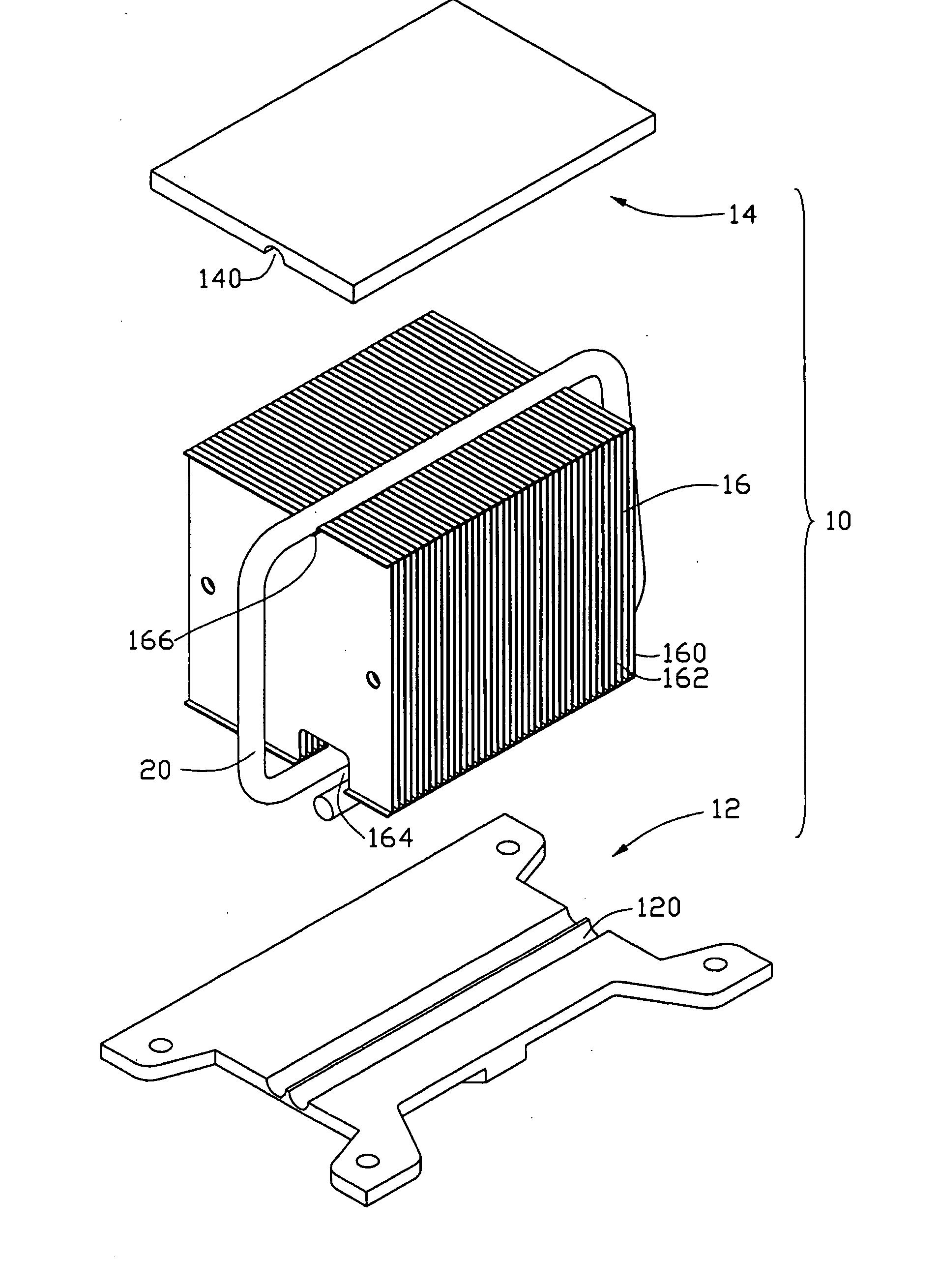
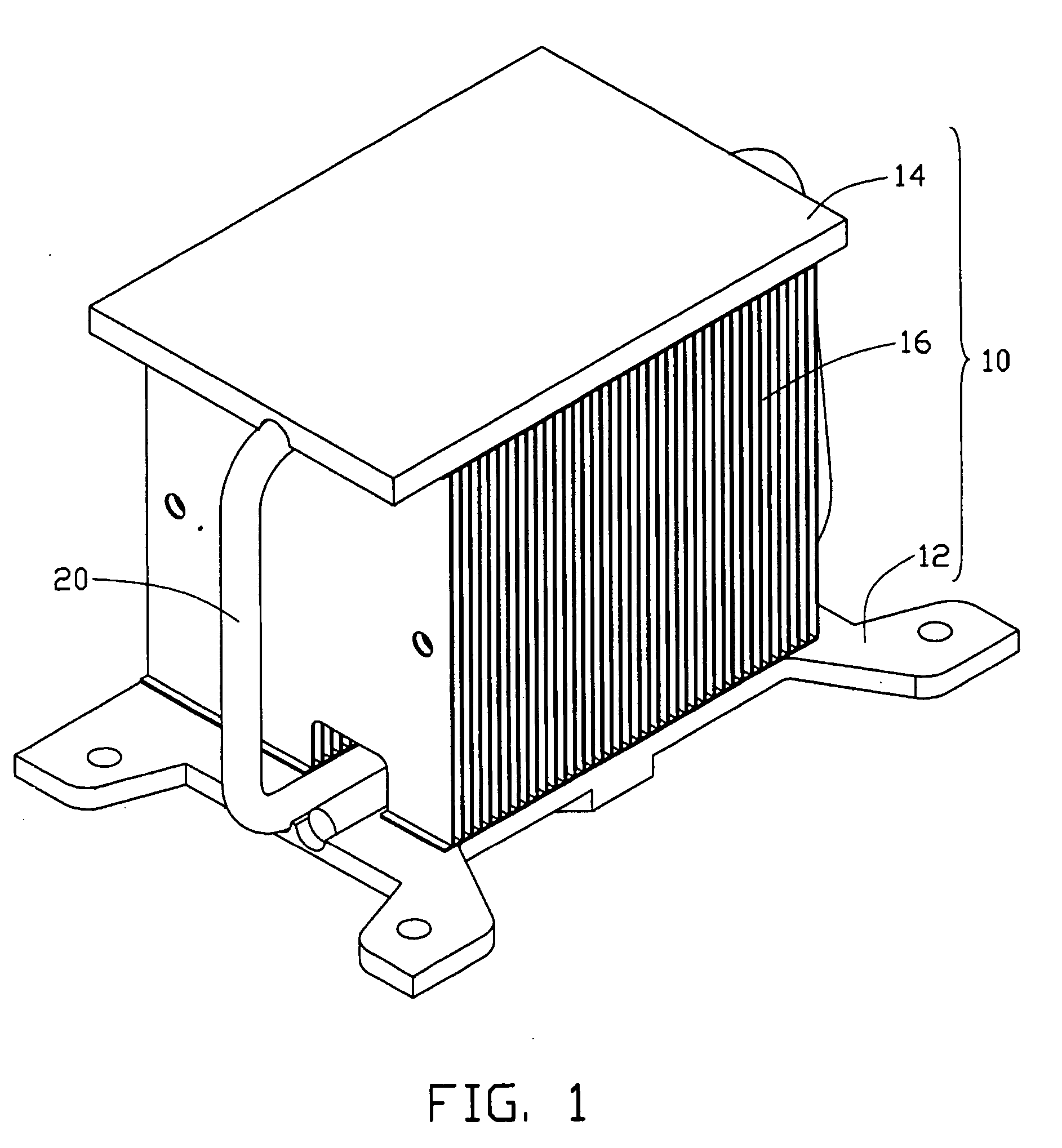
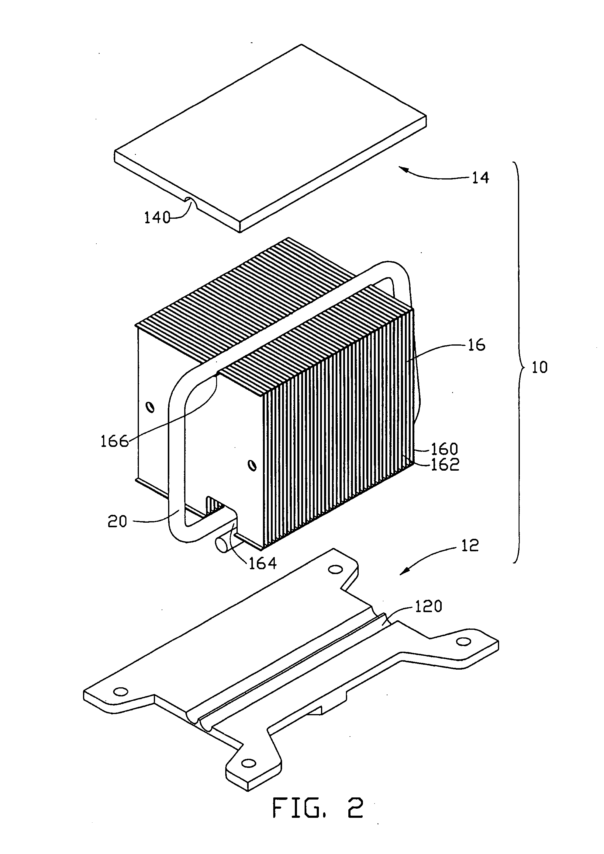
[0013]FIG. 1 shows a heat dissipation device in accordance with a preferred embodiment of the present invention. The heat dissipation device comprises a heat sink 10 and a heat pipe20.

[0014] Referring also to FIG. 2, the heat sink 10 comprises a base 12, a cover 14 spaced opposite to the base 12, and a fins group 16 sandwiched between the base 12 and the cover 14. A bottom surface of the base 12 is used for being attached to an electrical component (not shown). The base 12 defines a pair of first grooves 120 in a top surface thereof. The cover 14 defines a second groove 140 in a bottom surface thereof. The fins group 16 comprises a plurality of spaced heat dissipating fins 160. The spaced heat dissipating fins 160 define a plurality of air passageways 162 therebetween. Airflow flows through the air passageways 162 to take heat away from the fins 160. A bottom surface of the fins group 16 defines a first channel 164 corresponding to the first grooves 120. The first channel 164 coope...


PUM


Abstract

A heat dissipation device includes a heat sink (10) and a heat pipe (20). The heat sink includes a base (12), a fins group (16) extending from the base, and a cover (14) contacting with the fins group. The heat pipe surrounds top and bottom and two opposite sides of the fins group and thermally connects with the base and the cover.

Description

BACKGROUND [0001] 1. Field of the Invention [0002] The present invention relates generally to a heat dissipation device, and more particularly to a heat dissipation device using heat pipes for enhancing heat removal from heat-generating components. [0003] 2. Related Art [0004] As computer technology continues to advance, electronic components such as central processing units (CPUs) of computers are being made to provide faster operational speeds and greater functional capabilities. When a CPU operates at high speed in a computer enclosure, its temperature can increase greatly. It is desirable to dissipate the heat quickly, for example by using a heat dissipation device attached to the CPU in the enclosure. This allows the CPU and other electronic components in the enclosure to function within their normal operating temperature ranges, thereby assuring the quality of data management, storage and transfer. [0005] A conventional heat dissipation device comprises a heat sink and a heat ...

Claims


Application Information

Patent Timeline
Patent Type & Authority Applications(United States)
IPC IPC(8): H05K7/20
CPCH01L23/427H01L23/467H01L2924/0002H01L2924/00F28D15/0275
Inventor LEE, HSIEH-KUNLAI, CHENG-TIENTAN, ZHI-BINZHOU, ZHI-YONGWEN, JIANG-JIAN
Owner HON HAI PRECISION IND CO LTD
Why Eureka
Try Eureka