
Optoelectronic sensor device for a motor vehicle

Inactive Publication Date: 2007-05-03
LEOPOLD KOSTAL GMBH & CO KG
View PDF4 Cites 1 Cited by
  • Summary
  • Abstract
  • Description
  • Claims
  • Application Information

AI Technical Summary

Benefits of technology

[0009] An object of the present invention is an optoelectronic sensor for detecting moisture of a motor vehicle window (e.g., windshield) in which incident extraneous light coming through the window has a reduced influence on the receiver of the sensor.
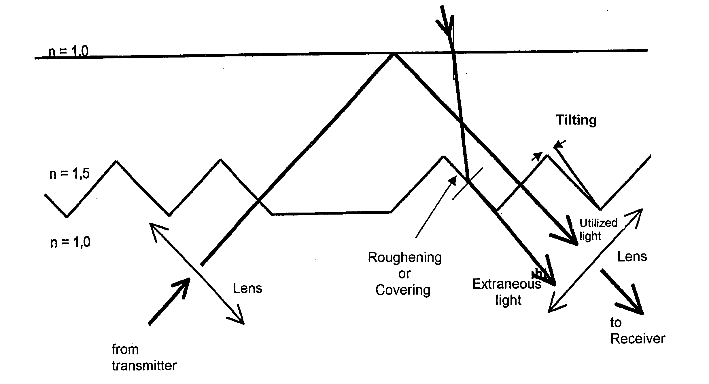
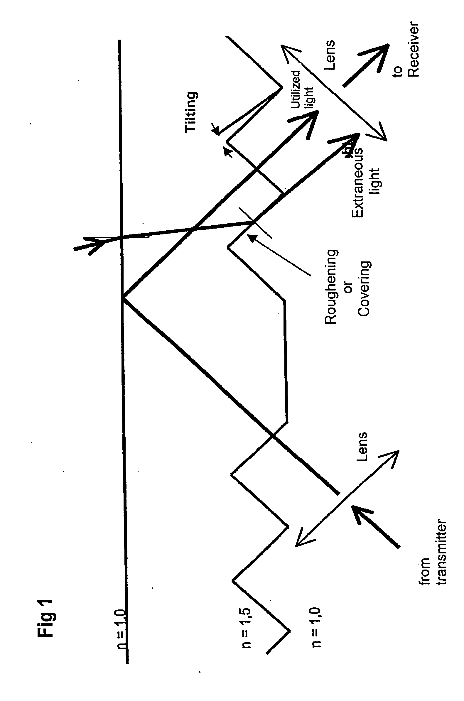
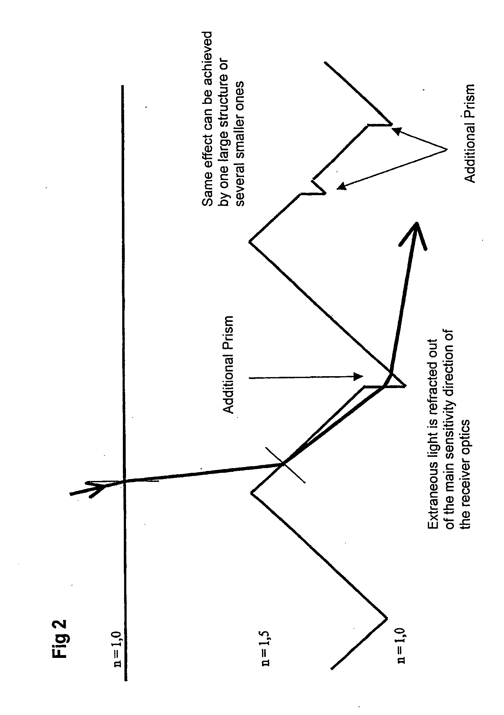
[0017] Thus, an optoelectronic sensor in accordance with the present invention includes measures to reduce the proportion of exiting extraneous light glancing off the prism flanks (i.e., edges) of the coupler. This may be accomplished by roughening or covering the prism flanks (which are parallel to the useful light) of the prisms of the coupler, by tilting the prism flanks, or by additional deflection of the glancing exiting extraneous light with additional prisms superimposed on the prisms of the coupler.

Problems solved by technology

A problem is extraneous light influences cannot be completely excluded.
Extraneous light reduces the sensitivity of such a sensor and may cause the sensor to trigger incorrectly.

Method used


Image

  • Optoelectronic sensor device for a motor vehicle
  • Optoelectronic sensor device for a motor vehicle
  • Optoelectronic sensor device for a motor vehicle

Examples


Embodiment Construction

)

[0022] Referring initially to FIG. 3, an optoelectronic sensor in accordance with the present invention is shown. The sensor senses rain, humidity, moisture, dirt, etc., on a pane 4. Pane 4 may be a window, windshield, glass pane, etc., of a motor vehicle. The sensor generally includes a light transmitter 5, a first lens 2, a coupler 1, a second lens 3, and a light receiver 6. The sensor is located on the interior side of pane 4. For instance, if pane 4 is a motor vehicle windshield, the sensor is located within the interior of the motor vehicle.

[0023] Light transmitter 5 includes a transmitting diode or the like for transmitting optical radiation. For instance, light transmitter 5 transmits optical radiation in the near infrared range at a wavelength of about 880 nm. Light receiver 6 includes a photodiode or the like for detecting optical radiation.

[0024] In operation, light transmitter 5 emits optical radiation towards first lens 2. First lens 2 converts the optical radiation i...


PUM


Abstract

A sensor for detecting moisture on a pane includes a coupler having prisms arranged in coupling areas for coupling light from a transmitter into the pane at an input angle and prisms arranged in decoupling areas for decoupling light reflected from the pane to a receiver at a corresponding output angle. The prisms in the coupling areas have prism surfaces perpendicular to the input angle and the prisms in the decoupling areas have prism surfaces perpendicular to the output angle. Each prism includes a prism flank. The prism flanks in the decoupling areas may be arranged parallel to the output angle. Some of the prism flanks in the decoupling areas are opaque or roughened. Alternatively, some of the prism flanks in the decoupling areas are tilted from running parallel to the output angle. Alternatively, some of the prism flanks in the decoupling areas include at least one additional superimposed prism.

Description

CROSS-REFERENCE TO RELATED APPLICATIONS [0001] This is a continuation of International Application PCT / EP2005 / 007471, published in German, with an international filing date of Jul. 9, 2005, which claims priority to DE 10 2004 033 734.9, filed Jul. 13, 2004, the disclosures of which are both hereby incorporated by reference.BACKGROUND OF THE INVENTION [0002] 1. Field of the Invention [0003] The present invention generally relates to an optoelectronic sensor for detecting moisture on a window and, more particularly, to such an optoelectronic sensor having a prism structure which couples radiation from a transmitter into the window and decouples reflected radiation out of the window towards a receiver in which the prism structure includes individual prisms having prism surfaces in coupling areas arranged perpendicular to the input radiation angle of incidence and prism surfaces in decoupling areas arranged perpendicular to the output radiation angle of incidence. [0004] 2. Background A...

Claims


Application Information

Patent Timeline
IPC IPC(8): H01J3/14H01J40/14H01J5/16
CPCB60S1/0822B60S1/0833G01N21/552
Inventor RICHWIN, MATTHIASWEBER, THOMAS
Owner LEOPOLD KOSTAL GMBH & CO KG
Learn More