Sliding door arrangement for a motor vehicle

a technology for sliding doors and motor vehicles, applied in the direction of doors, lock applications, roofs, etc., can solve the problems of small holding forces needed for this purpose, and achieve the effects of high crash safety, economical structure, and great ease of us

Inactive Publication Date: 2007-05-03
BROSE SCHLIESSSYSTEME GMBH & CO KG
View PDF13 Cites 35 Cited by
  • Summary
  • Abstract
  • Description
  • Claims
  • Application Information

AI Technical Summary

Benefits of technology

[0013] A primary object of the present invention is to embody and develop the known sliding door arrangement such that a high level of crash safety is obtained, on the one hand, and great ease of use is achieved, on the other hand, with a compact, and at the same time, economical structure.
[0018] With respect to the different “quality” of the two aforementioned functions, in accordance with the invention, it is provided that the pretensioning of the catch lever in the direction of the engaged state rises by the movement of the sliding door into the closed position. This means, first of all, that the pretensioning of the catch lever is minimal when the sliding door is in the opened position. This leads to the fact that the catch lever can be raised with minimum force. In the case of manual actuation, in turn, this means great ease of use.
[0019] When the sliding door is in the closed position, the pretensioning of the catch lever is conversely maximum. This means that the catch lever is pressed with high pretensioning into the engaged state. In the case of a crash, this means that the unwanted raising of the catch lever which is caused by the acceleration forces there is avoided. Crash safety is increased by the increased pretensioning of the catch lever.
[0022] According to another teaching which acquires independent importance, there is a catch lever which is used both for fixing the sliding door in the opened position and also for fixing the sliding door in the closed position. In this connection, it has been recognized that the construction configuration of the catch lever is especially simple when the catch lever for fixing the sliding door in one position of the sliding door works as a hooked catch lever, and as a support catch lever in the other position of the sliding door. This means that the catch lever is, on the one hand, loaded by tension, and on the other hand, by pressure. As in a preferred embodiment, it can be easily provided that a hook-shaped portion for operation as a hooked catch lever and a support section for operation as a support catch lever are located on an arm of the catch lever. This leads to an especially compact, and at the same time, durable configuration of the catch lever.
[0023] According to another teaching which likewise acquires independent importance, the lock arrangement is equipped with the conventional latching elements, i.e., a latch and ratchet, which provide for fixing of the sliding door in the closed position. This further independent teaching is based on the consideration that the ratchet can be used for two purposes here. The ratchet can be used specifically in addition to fix the sliding door in the opened position. In doing so, the ratchet fundamentally assumes the function of the hooked and support catch lever explained above. This double use of the ratchet allows a further increase of compactness.
[0024] In all the above described sliding door arrangements, it is preferably provided that the lock arrangement has a main lock arrangement by which the sliding door can be fixed in the closed position, and an auxiliary lock arrangement to support the main lock arrangement. In this connection, the above described catch lever arrangements and the above described latch arrangement with the latch and ratchet are preferably assigned to the auxiliary lock arrangement. Especially high crash safety can be achieved by the main lock arrangement, on the one hand, and the auxiliary lock arrangement, on the other hand, being located on opposite regions of the sliding door viewed in the lengthwise direction of the motor vehicle. The main lock arrangement, in turn, preferably, has the latch elements latch and ratchet.

Problems solved by technology

Furthermore, the holding forces necessary for this purpose are small.

Method used


Image

  • Sliding door arrangement for a motor vehicle
  • Sliding door arrangement for a motor vehicle
  • Sliding door arrangement for a motor vehicle

Examples


Embodiment Construction

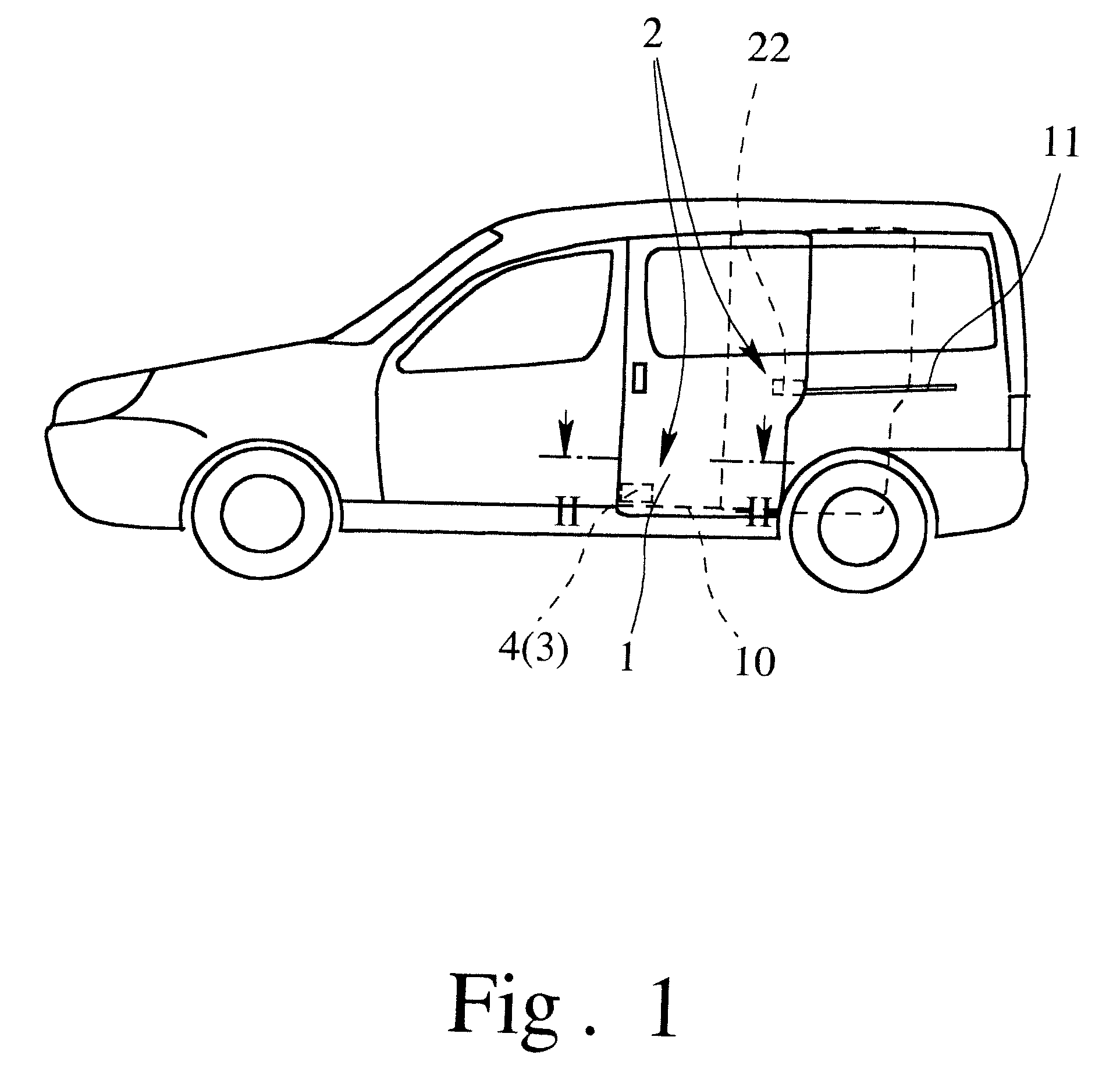
[0032] In the drawings, FIG. 1 shows a motor vehicle with a sliding door arrangement which is located laterally on the vehicle. It is also equally possible for the sliding door arrangement to be located on the back of the motor vehicle. The sliding door arrangement has a sliding door 1 which can be moved by a sliding motion into an opened position (shown in FIG. 1 in broken lines) and into a closed position (shown in FIG. 1 in solid lines). The configuration of the guide of the sliding door 1 is detailed below.

[0033] To fix the sliding door 1 in the opened position, on the one hand, and in the closed position, on the other hand, there is a lock arrangement 2. Basically, the lock arrangement 2 can also be used to fix the sliding door 1 in the intermediate position.

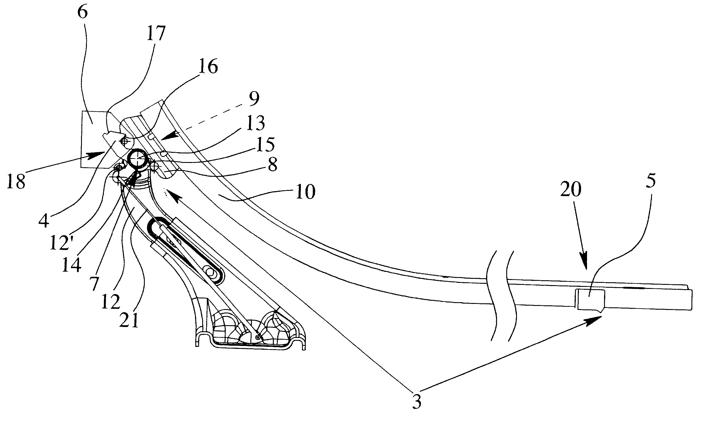
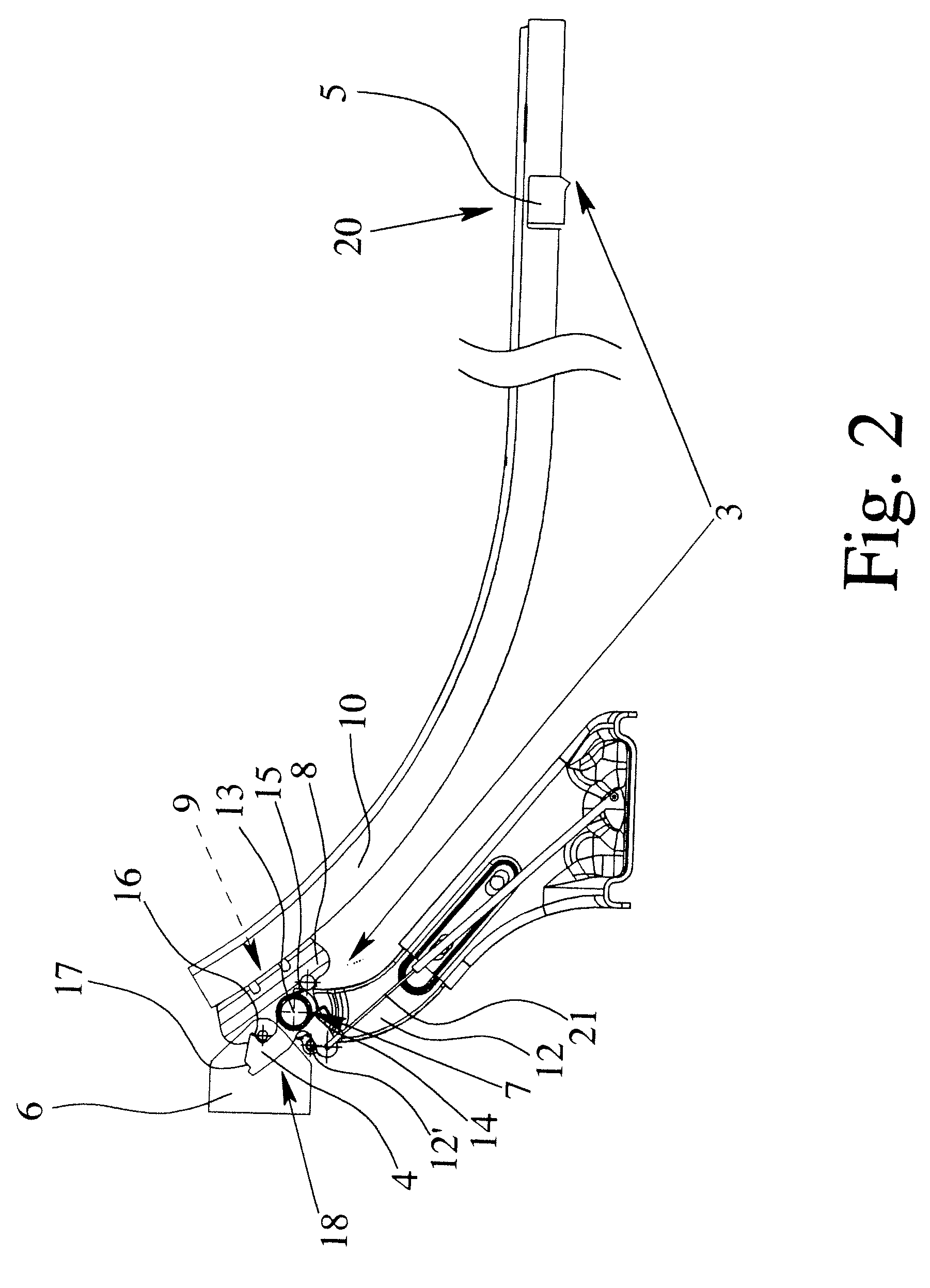
[0034] The lock arrangement 2 is equipped here with a catch lever arrangement 3 which has a pivoting catch lever 4. The catch lever 4 can be moved into the engaged state (FIG. 2, FIG. 4) and into the raised state (FIG. 3)...


PUM


Abstract

Sliding door arrangement for a motor vehicle having a lock arrangement, for fixing a sliding door in opened and closed positions, with a catch lever arrangement with a pivoting catch lever that is movable into engaged and raised states and is pretensioned toward the engaged state. The catch lever arrangement has first and second engagement elements with which the catch lever engageable, the catch lever, when the sliding door is in the opened position, engaging the first engagement element and the catch lever fixing the sliding door in the opened position. The catch lever is engageable with the second engagement element when the sliding door is in the closed position and the catch lever fixes the sliding door in the closed position. The arrangement is such that the pretensioning of the catch lever toward the engaged state rises by the movement of the sliding door into the closed position.

Description

BACKGROUND OF THE INVENTION [0001] 1. Field of the Invention [0002] This invention relates to a sliding door arrangement for a motor vehicle in which the sliding door is slidable into opened and closed positions, and in which a lock arrangement is provided for fixing the sliding door in the opened and in the closed position, the lock arrangement having a catch lever arrangement, the catch lever arrangement having a pivoting catch lever, the catch lever being movable into an engaged state and into a raised state and being pretensioned into the engaged state, the catch lever arrangement having a first engagement element and a second engagement element which the catch lever engages is in an engaged state, the catch lever, when the sliding door is in the opened position being able to engage the first engagement element and the catch lever which is then in the engaged state fixing the sliding door in the opened position. [0003] The invention is also directed to a sliding door arrangement...

Claims


Application Information

Patent Timeline
Patent Type & Authority Applications(United States)
IPC IPC(8): B60J5/06
CPCB60J5/06E05B65/0852E05C17/62E05D15/1047E05Y2900/531E05B79/20E05B83/40Y10S292/23
Inventor KOTHE, MARKUSHOERSCHGEN, FRANK
Owner BROSE SCHLIESSSYSTEME GMBH & CO KG
Why Eureka
Try Eureka