
Organic light emitting diode display and method of manufacturing the same

Inactive Publication Date: 2007-05-03
SAMSUNG DISPLAY CO LTD
View PDF19 Cites 59 Cited by
  • Summary
  • Abstract
  • Description
  • Claims
  • Application Information

AI Technical Summary

Benefits of technology

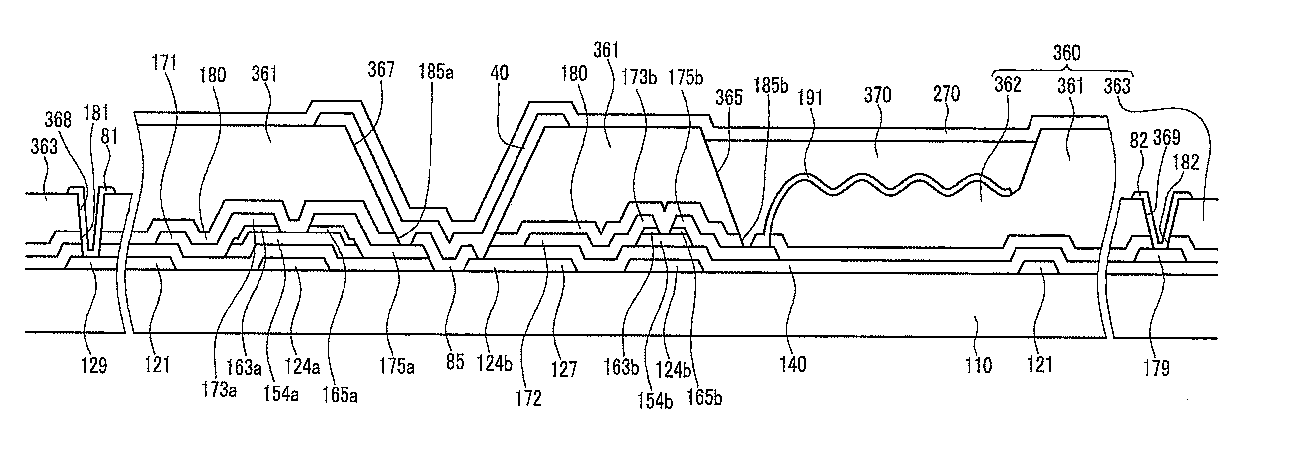
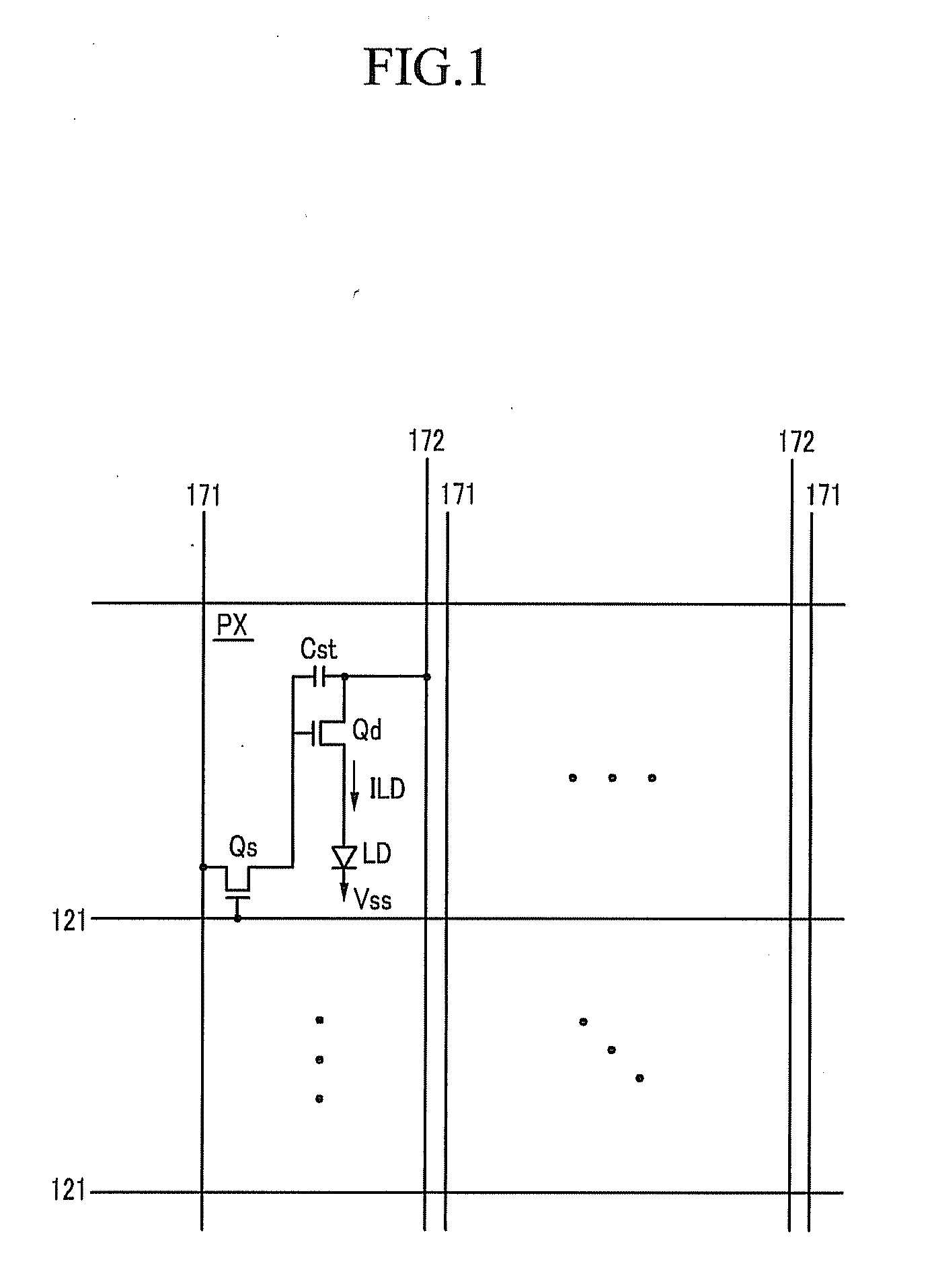
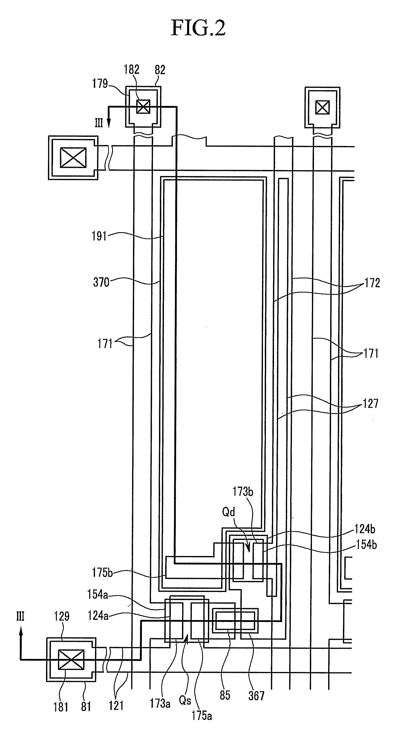
[0017] An aspect of the present invention is to provide an organic light emitting diode display and method of manufacturing the same that is capable of reducing the number of masks, thereby simplifying the manufacturing processes, and at the same time increasing a light emitting amount per unit pixel.

Problems solved by technology

Reflective LCDs may use ambient light in order to display images, however they are not ideal for all applications.
In addition, LCDs have limitations in their response speed and a viewing angle.
However, since the partition walls are formed by a photolithography process, the number of masks for the process increases, thereby increasing manufacturing costs.
However, there is a limitation to the efficiency obtainable from a light emitting material.

Method used


Image

  • Organic light emitting diode display and method of manufacturing the same
  • Organic light emitting diode display and method of manufacturing the same
  • Organic light emitting diode display and method of manufacturing the same

Examples


Embodiment Construction

[0087] The invention now will be described more fully hereinafter with reference to the accompanying drawings, in which embodiments of the invention are shown. This invention may, however, be embodied in many different forms and should not be construed as limited to the embodiments set forth herein. Rather, these embodiments are provided so that this disclosure will be thorough and complete, and will fully convey the scope of the invention to those skilled in the art. Like reference numerals refer to like elements throughout.

[0088] It will be understood that when an element is referred to as being “on” another element, it can be directly on the other element or intervening elements may be present therebetween. In contrast, when an element is referred to as being “directly on” another element, there are no intervening elements present. As used herein, the term “and / or” includes any and all combinations of one or more of the associated listed items.

[0089] It will be understood that,...


PUM


Abstract

A method of manufacturing an organic light emitting diode display includes forming a plurality of signal lines and a plurality of TFTs on a substrate, forming a passivation layer on the signal lines and the TFTs, forming a photosensitive layer having a plurality of openings on the passivation layer, etching the passivation layer using the photosensitive layer as a mask, forming a first electrode by depositing and etching a conductive layer on substantially the entire surface including the photosensitive layer, forming a light emitting member in portions of the openings, and forming a second electrode on the light emitting member and the photosensitive layer.

Description

[0001] This application claims priority to Korean Patent Application No. 10-2005-0102250 and Korean Patent Application No. 10-2005-0102254, both filed on Oct. 28, 2005, the contents of which in their entirety are herein incorporated by reference. BACKGROUND OF THE INVENTION [0002] (a) Field of the Invention [0003] The present invention relates to an organic light emitting diode (“OLED”) display and a method of manufacturing the same. [0004] (b) Description of the Related Art [0005] Recently, thin and light-weight types of monitors and television sets have grown in popularity. Cathode ray tubes (“CRTs.”) have been increasingly replaced by liquid crystal displays (“LCDs”). [0006] However, since the LCD is a non-emissive display device, a backlight is needed in the construction of most LCD displays. Reflective LCDs may use ambient light in order to display images, however they are not ideal for all applications. In addition, LCDs have limitations in their response speed and a viewing a...

Claims


Application Information

Patent Timeline
IPC IPC(8): H05B33/08H05B33/10H01L51/50H05B44/00
CPCH01L27/3246H01L51/5203H01L51/5284H01L51/56H10K59/122H10K71/00H10K59/805H10K59/8792H10K50/805H10K50/865
Inventor PARK, SEUNG-KYUHUH, JONG-MOOKIM, NAM-DEOGSHIN, KYOUNG-JU
Owner SAMSUNG DISPLAY CO LTD
Learn More