Laser type coordinate sensing system for touch module

a coordinate sensing system and touch module technology, applied in the field of touch position sensors, can solve the problems of insufficient mechanical endurance and durability of the touch panel, inability to accurately detect the coordinate position of the touch point, etc., to achieve accurate and precise detection of the coordinate position of any point in the touch area, and improve the effect of electrical properties

Inactive Publication Date: 2007-05-03
ZEBEX IND
View PDF3 Cites 11 Cited by
  • Summary
  • Abstract
  • Description
  • Claims
  • Application Information

AI Technical Summary

Benefits of technology

[0007] A primary object of the present invention is to provide a laser type coordinate sensing system for touch module capable of accurately and precisely sensing coordinate positions of a touched point. The system produces a plurality of densely and orthogonally intersected laser beams in a touch area on a surface, so that coordinate positions of a point in the touch area touched by a user's finger may be easily calculated from changes in laser beams being received in the system.
[0008] Another object of the present invention is to provide a laser type coordinate sensing system for touch module that may be associated with a display panel, so that an operator may easily control a target apparatus simply by touching the display panel.
[0010] As compared with the conventional touch display, the laser type coordinate sensing system for touch module according to the present invention effectively overcomes the problems of inaccurate detection of coordinate positions, changed electric properties, poor durability, etc. With the a plurality of densely and orthogonally intersected laser beams formed in the touch area on a touch panel or touch display, it is possible to accurately and precisely detect the coordinate positions of any point in the touch area touched by an operator's finger. Moreover, since laser beam technique is employed in the present invention, the whole coordinate sensing system has stable electric properties that do change with time. Further, the present invention is more durable than other conventional coordinate sensing structures.

Problems solved by technology

In practical use of the conventional touch display, the coordinate positions of the touched point are not always accurately detected.
There are also other problems, such as insufficient mechanical endurance and durability of the touch panel.
For example, in the currently available thin-film resistive touch screen technique, the spacer dot matrix provided between the upper and lower touch layers does not provide accurate coordinate position detection when the touch layers are touched.
Moreover, the thin-film resistive coating on the touch screen tends to change in electric properties after being used over a period of time, and would therefore adversely affect the operation and accuracy of the touch panel.
Moreover, the thin-film resistive touch screen would be damaged and become useless when the surface of the touch layers is scratched by a sharp article.

Method used


Image

  • Laser type coordinate sensing system for touch module
  • Laser type coordinate sensing system for touch module
  • Laser type coordinate sensing system for touch module

Examples


Embodiment Construction

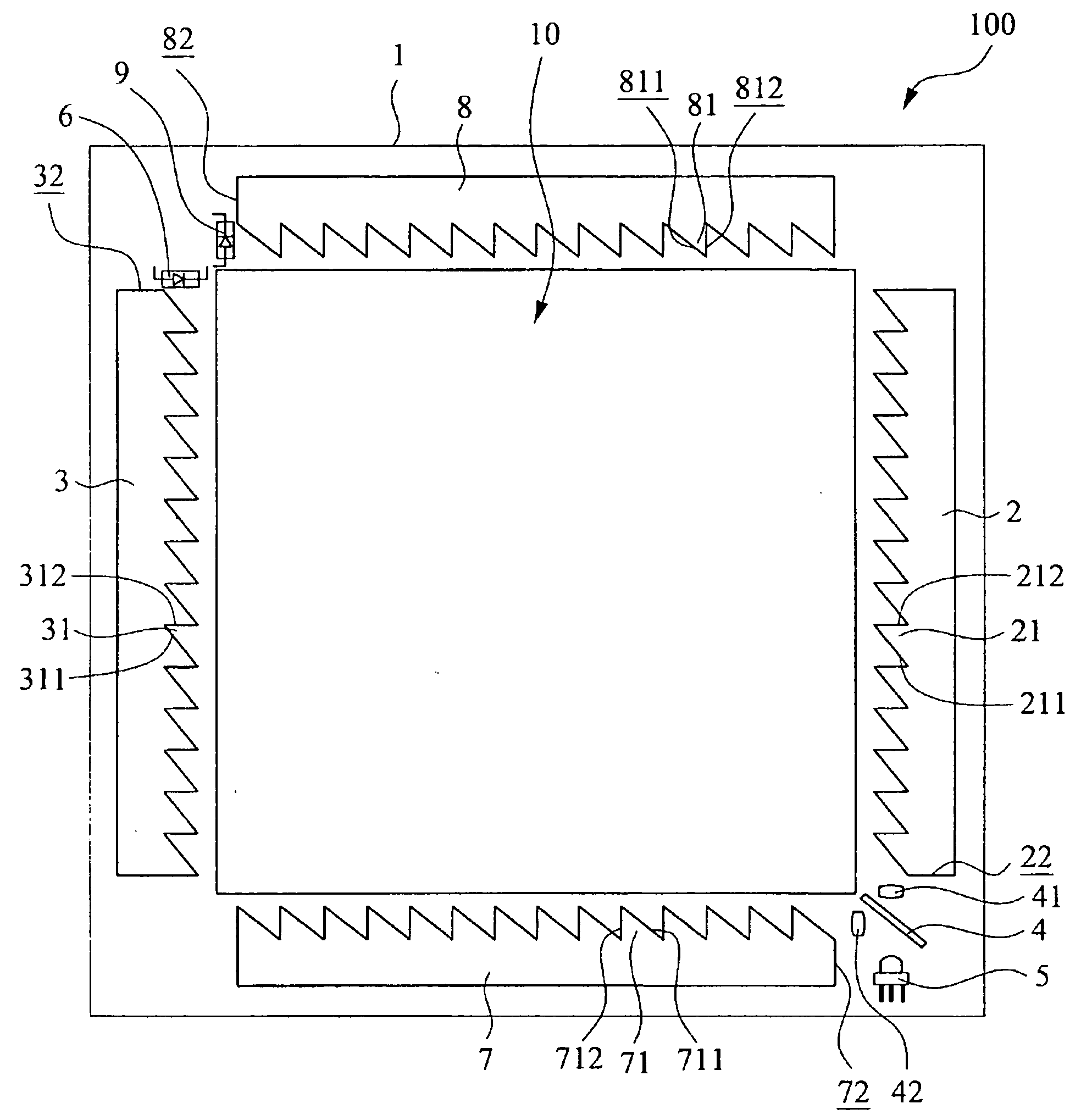
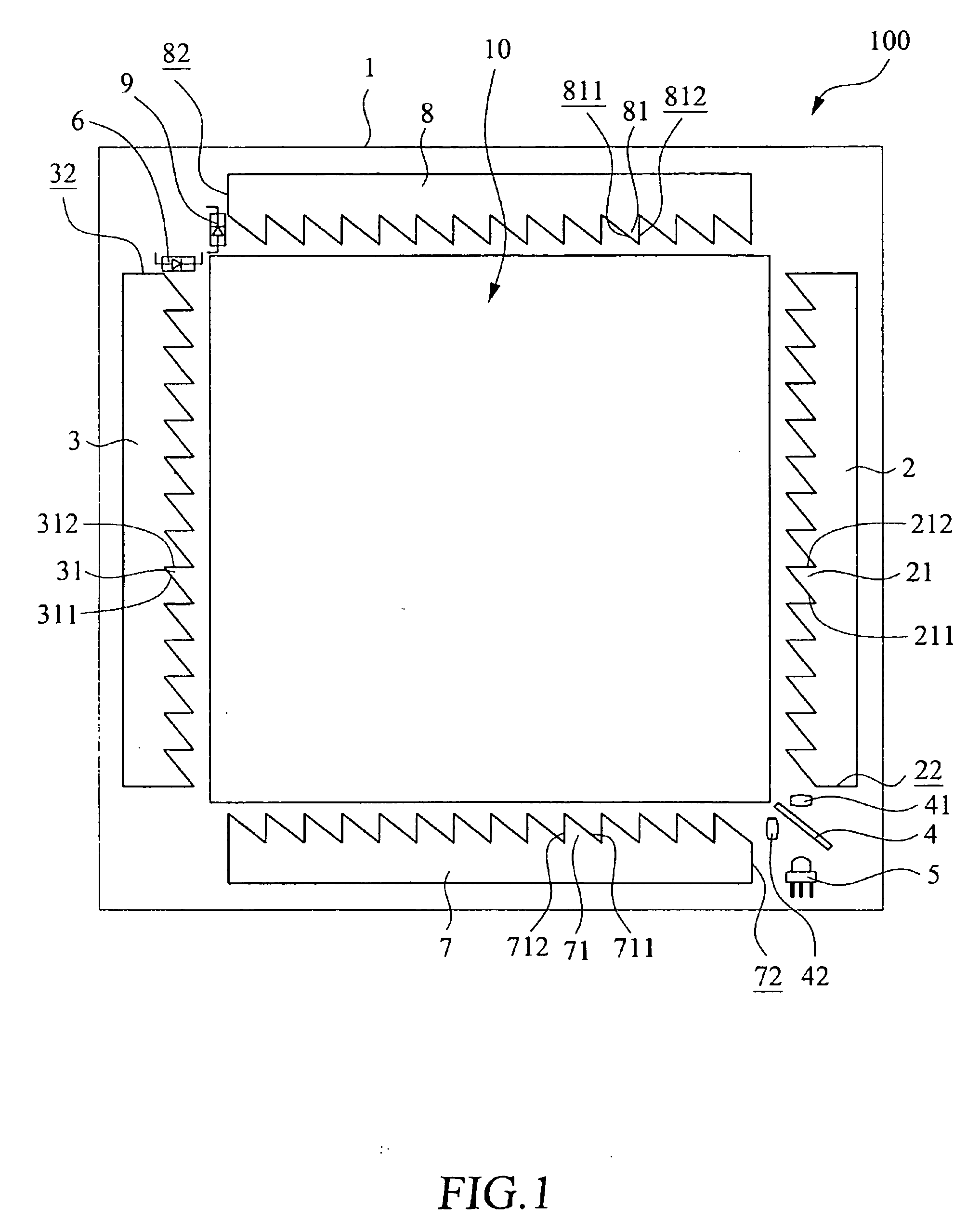
[0022] Please refer to FIG. 1 that is a plan view showing a laser type coordinate sensing system for touch module according to a first embodiment of the present invention. For the purpose of conciseness, the present invention is also briefly referred to as “the coordinate sensing system” throughout this specification. As shown, the coordinate sensing system according to the first embodiment of the present invention is generally denoted a numeral reference 100, and includes a substrate 1. On a surface of the substrate 1, there is defined a touch area 10, within which a user may effectively execute touch-control operation.

[0023] An X-direction light emitting array 2 is provided to one vertical side of the touch area 10, and an X-direction light receiving array 3 is provided to another vertical side of the touch area 10 opposite to and corresponding to the X-direction light emitting array 2. The X-direction light emitting array 2 includes a plurality of laser light emitting units 21 l...


PUM


Abstract

A laser type coordinate sensing system for touch module includes an X-direction light emitting array, an X-direction light receiving array, a Y-direction light emitting array, and a Y-direction light receiving array provided at four sides of a touch area on a substrate, so that a plurality of X-direction laser beams projected from the X-direction light emitting array and a plurality of Y-direction laser beams projected from the Y-direction light emitting array densely and orthogonally intersect with one another in the touch area on the substrate. The laser type coordinate sensing system for touch module may be associated with a display panel to form a laser type touch panel.

Description

FIELD OF THE INVENTION [0001] The present invention relates to a touch position sensor, and more particularly to a laser type coordinate sensing system for touch module. The coordinate sensing system produces a plurality of densely and orthogonally intersected laser beams in a touch area on a substrate, so as to sense coordinate positions of a point in the touch area touched by a user's finger. BACKGROUND OF THE INVENTION [0002] With various kinds of powerful functions, such as word processing, equipment controlling, drawing, game software executing, and multimedia production and playback, computer has become more and more important to all kinds of business. Time being spent by people everyday in operating computers is increasingly extended. Among others, computer research and development engineers, secretarial staff, data input operators, etc. spend particularly long time in work hours to use various kinds of computer-related input devices, such as keyboard, mouse, touch panel, tou...

Claims


Application Information

Patent Timeline
Patent Type & Authority Applications(United States)
IPC IPC(8): G09G5/00
CPCG06F3/0421
Inventor LIAO, JERRY
Owner ZEBEX IND
Why Eureka
Try Eureka