Multi-user stereoscopic 3-D panoramic vision system and method

a multi-user, panoramic technology, applied in the field of sensors and displays, can solve the problems of not being able to share non-coincident stereo views of the outside of the vehicle, not being able to simultaneously acquire and display data panoramically, at its true resolution, in real-time, as three-dimensional (3-), severely hampered the ability to implement adequate operator interfaces, etc., to reduce collateral or unintended damage

Inactive Publication Date: 2007-05-03
HARRIS CORP
View PDF18 Cites 212 Cited by
  • Summary
  • Abstract
  • Description
  • Claims
  • Application Information

AI Technical Summary

Benefits of technology

[0012] Another advantage of the present invention is found in the near-zero lag time between the time the scene is captured and the time it is presented to the operator(s), irrespective of the directions(s) the operator(s) may be looking in.
[0013] Still another advantage of the present development resides in its ability to calculate the coordinates (e.g., x, y, z) of an object or objects located within the field of view.
[0014] Still another advantage of the present invention is the ability to link the scene presented to the operator, the location of objects in the stereo scenes vi...

Problems solved by technology

Although it has been possible to collect panoramic images and even spherical images for a number of years, it has not been possible to simultaneously acquire and display data panoramically, at its true resolution, in real-time, as three-dimensional (3-D) stereoscopic images.
Nor has it been possible to share non-coincident stereo views of the outside of a vehicle.
The lack of these capabilities has severely hampered the ability to implement adequate operator interfaces in those vehicles that do not allow the operator to have direct view of the outside world, such as fighting vehicles like tanks and armored personnel carriers, among many other applications.
Personnel often prefer to have themselves partially out of the vehicle hatches in order to gain the best visibility possible, putting them at risk of casualty.
In the case of tanks, the risk to such personnel includes being hit by shrapnel, being shot by snipers, getting pinned by the vehicle when it rolls, as well as injuring others and property due to poor visibility around the vehicle as it moves.
Previous attempts at mitigating these problems include the provision of windows, periscopes, various combinations of displays and cameras, but none of these has provided a capability that mitigates the lack of view for the operators.
Hence, operators still prefer direct viewing, with its inherent dangers.
Windows must be small and narrow since they will not withstand ballistics and hence provide only a narrow field of view.
Periscopes have a narrow field of view and expose the operator to injury, e.g., by being str...

Method used


Image

  • Multi-user stereoscopic 3-D panoramic vision system and method
  • Multi-user stereoscopic 3-D panoramic vision system and method
  • Multi-user stereoscopic 3-D panoramic vision system and method

Examples


Embodiment Construction

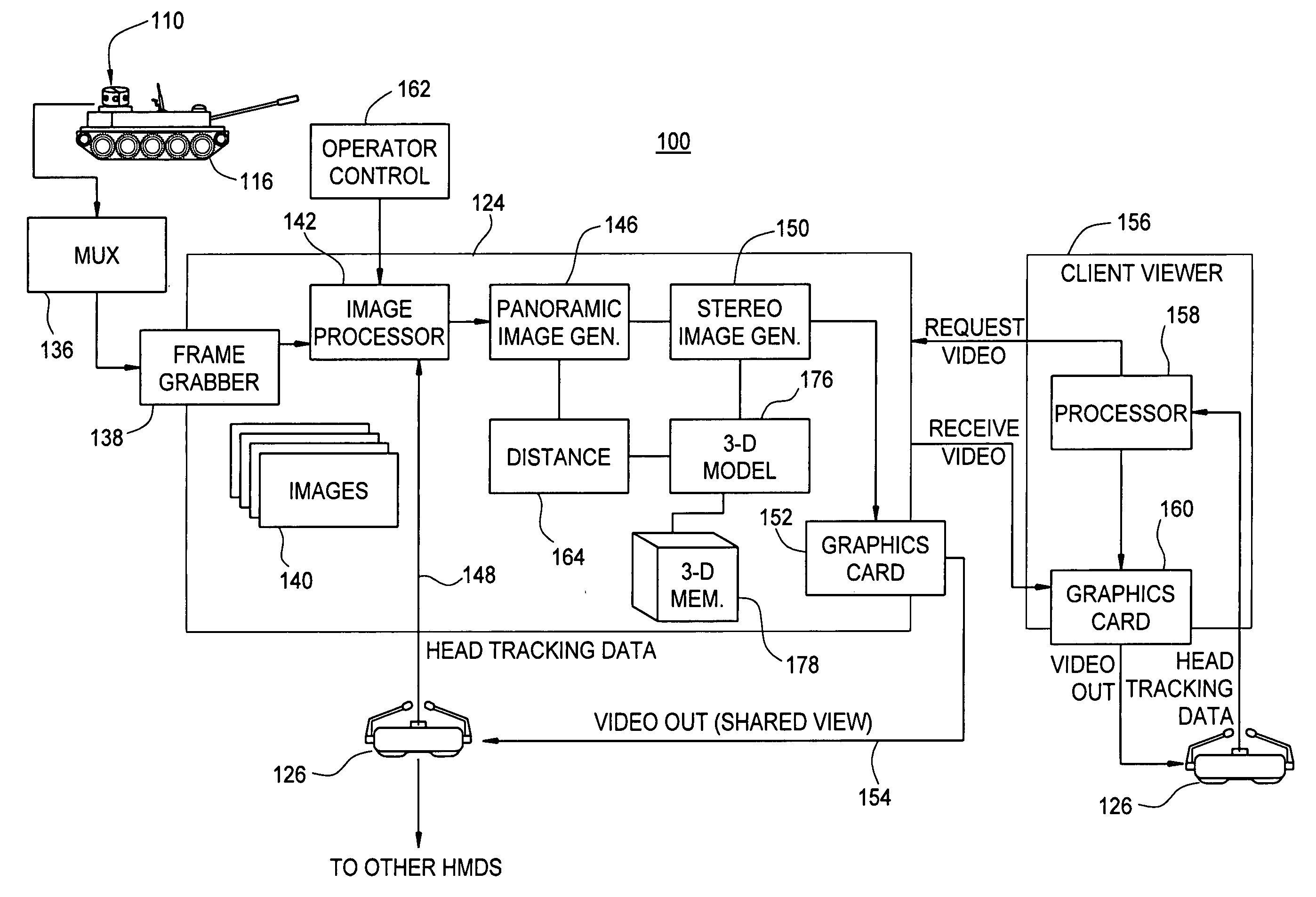
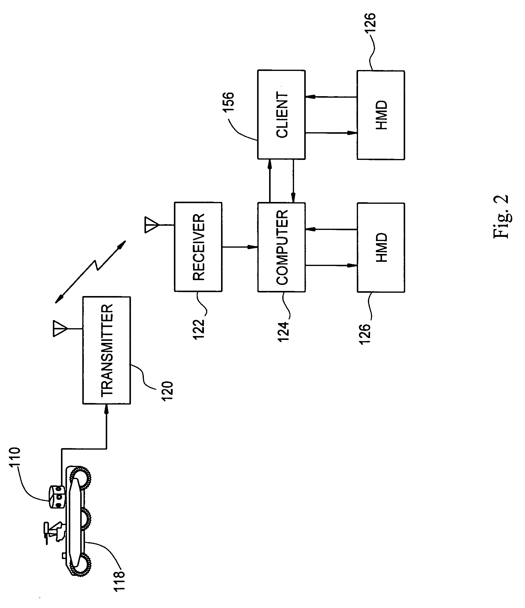
[0025] Referring now to the drawing figures, FIG. 1 depicts an exemplary vision system embodiment 100 employing an array 110 of sensors 112. An enlarged view of an exemplary sensor array 110 appears in FIG. 3. The sensor array 110 may include a housing 114 enclosing the plurality of sensors 112. The sensor array 110 is mounted on a vehicle 116, which is a tank in the depicted embodiment, although other vehicle types are contemplated, including all manner of overland vehicles, watercraft, and aircraft. Alternatively, the vision system of the present invention may be employed in connection with other types of structures or enclosures. For example, in FIG. 2, there is shown another exemplary embodiment wherein the camera array 110 is employed in connection with an unmanned, remotely operated vehicle 118. The vehicle includes an onboard transmitter, such as a radio frequency transmitter 120 for transmitting video signals from the sensor unit 110 to a receiver 122 coupled to a computer 1...


PUM


Abstract

A panoramic camera system includes a plurality of camera units mounted in a common, e.g., horizontal, plane and arranged in a circumferential array. Each camera unit includes one or more lenses for focusing light from a field of view onto an array of light-sensitive elements. A panoramic image generator combines electronic image data from the multiplicity of the fields of view to generate electronic image data representative of a first 360-degree panoramic view and a second 360-degree panoramic view, wherein the first and second panoramic views are angularly displaced. A stereographic display system is provided to retrieve operator-selectable portions of the first and second panoramic views and to display the user selectable portions in human viewable form. In a further aspect, a video display method is provided.

Description

BACKGROUND OF THE INVENTION [0001] The present invention relates generally to the art of sensors and displays. It finds particular application in vision systems for operators of manned and unmanned vehicles and is illustrated and described herein primarily with reference thereto. However, it will be appreciated that the present invention is also amenable to surveillance and other tele-observation or tele-presence applications and all manner of other panoramic or wide-angle video photography applications. [0002] Although it has been possible to collect panoramic images and even spherical images for a number of years, it has not been possible to simultaneously acquire and display data panoramically, at its true resolution, in real-time, as three-dimensional (3-D) stereoscopic images. Nor has it been possible to share non-coincident stereo views of the outside of a vehicle. The lack of these capabilities has severely hampered the ability to implement adequate operator interfaces in tho...

Claims


Application Information

Patent Timeline
IPC IPC(8): H04N5/14
CPCG03B35/08G03B35/20G03B37/04H04N5/232H04N5/23238H04N5/2627H04N13/0242H04N13/0282H04N13/044H04N13/0468H04N13/047H04N13/243H04N13/282H04N13/344H04N13/366H04N13/368H04N23/661H04N23/698H04N23/63
Inventor HOUVENER, ROBERT C.PRATTE, STEVEN N.
Owner HARRIS CORP
Why Eureka
Try Eureka