Variable polarization attenuator

a variable polarization attenuator and attenuator technology, applied in the direction of distance measurement, instruments, surveying and navigation, etc., can solve the problems of eye hazards, ground crews could be exposed to eye hazards, and laser types used

Inactive Publication Date: 2007-05-03
ROSEMOUNT AEROSPACE
View PDF4 Cites 27 Cited by
  • Summary
  • Abstract
  • Description
  • Claims
  • Application Information

AI Technical Summary

Benefits of technology

[0004] This Summary is provided to introduce a selection of concepts in a simplified form that are further described below in the Detailed Description. This Summary is not intended to identify key features or essential features of the claimed subject matter, nor is it intended to be used as an aid in determining the scope of the claimed subject matter.
[0005] In accordance with an example embodiment, a laser transmitting system includes a laser source configured to transmit a laser beam at an original transmit intensity. The system also includes a laser intensity adjusting mechanism positioned in the path of the transmitted laser beam. The laser intensity adjusting mechanism is controllable to reduce the intensity of the laser beam fro

Problems solved by technology

One potential problem with some lidar systems relates to the types of lasers used.
Many of these lasers emit light in the visible and near infrared wavelengths, which can be an eye hazard if the beam intensity is too high.
However, while the airc

Method used


Image

  • Variable polarization attenuator
  • Variable polarization attenuator
  • Variable polarization attenuator

Examples


Embodiment Construction

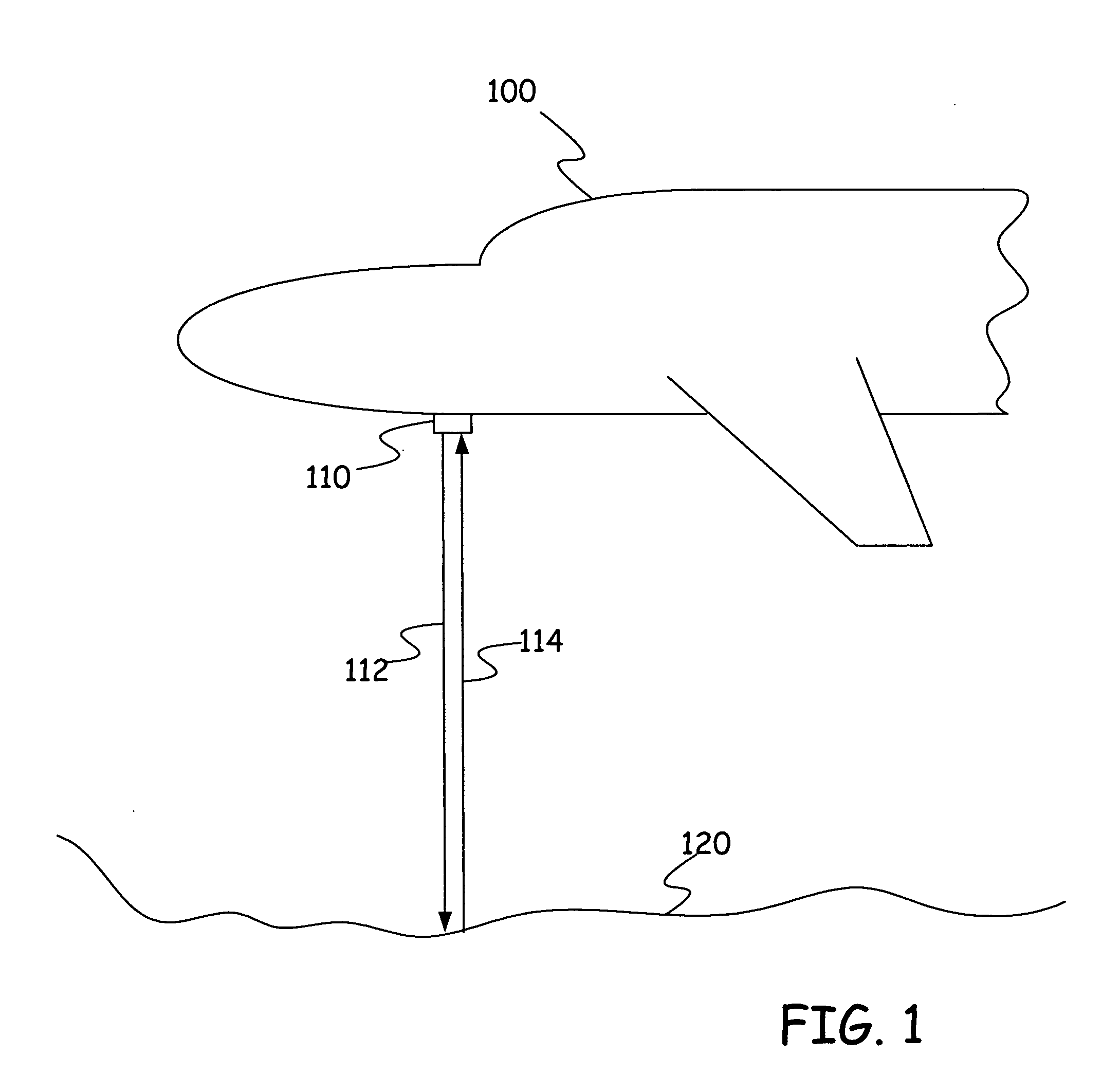
[0013]FIG. 1 is a diagrammatic illustration of an aircraft 100 with a laser transmitting system 110 in accordance with disclosed embodiments. Laser transmitting system 110 is, in exemplary embodiments, a lidar system, for example a laser altimeter system. This type of laser transmitting system 110 can be used to transmit a laser beam 112 toward a surface 120 (for example the ground, a structure or other types of surfaces). By detecting the reflected energy 114, system 110 can detect the presence of surface 120. Based upon the timing between transmission of laser beam 112 and detection of reflected energy 114, a range or distance between system 110 (and thus aircraft 100) and surface 120 can be estimated using well known techniques.

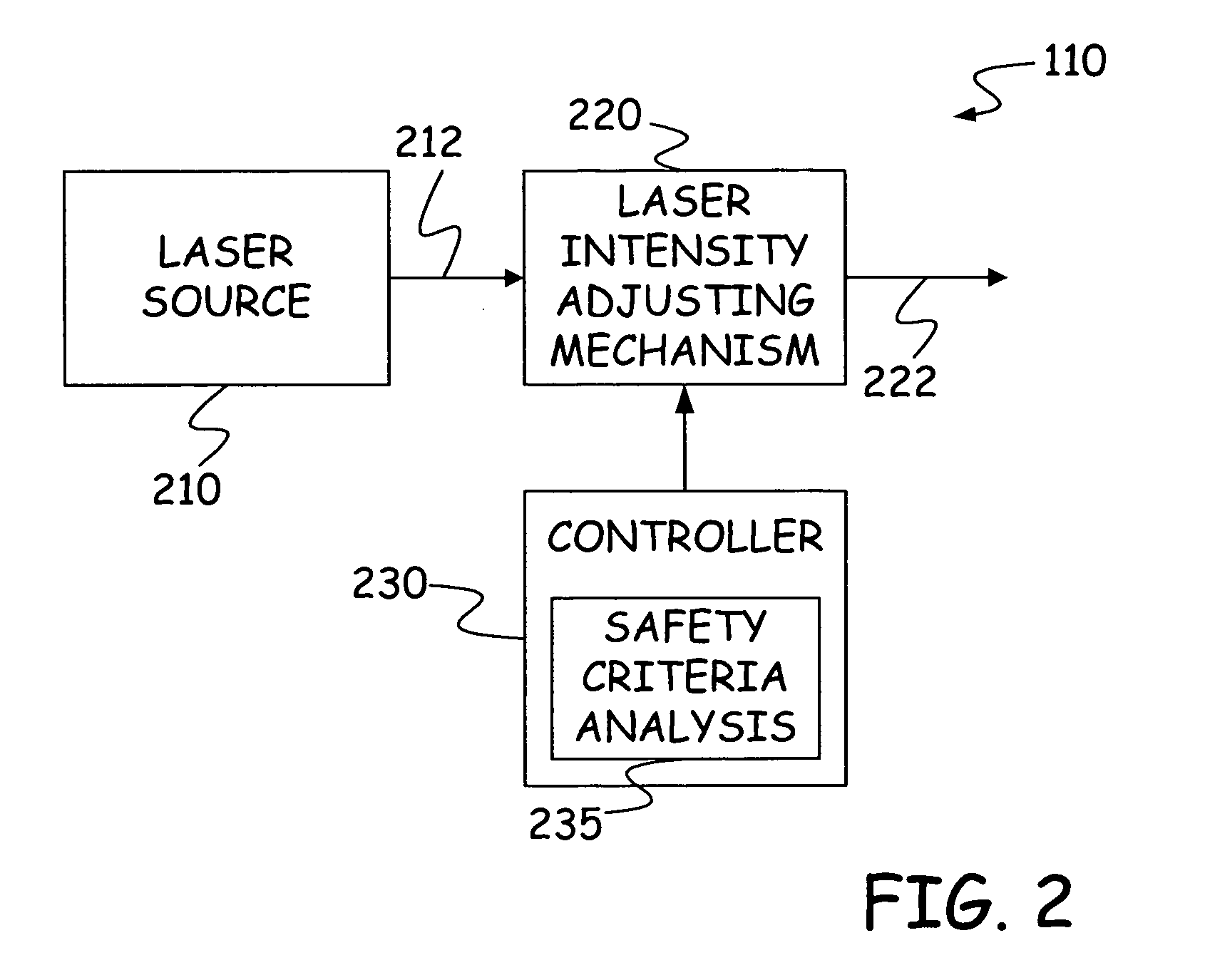
[0014] As noted above, lidar systems frequently use laser sources that emit light in the visible and near infrared wavelengths, which can be an eye hazard if the beam intensity is too high. On the other hand, if the beam intensity is not high enough at hi...


PUM


Abstract

A laser transmitting system includes a laser source configured to transmit a laser beam at an original transmit intensity. The system also includes a laser intensity adjusting mechanism positioned in the path of the transmitted laser beam. The laser intensity adjusting mechanism is controllable to reduce the intensity of the laser beam from the original transmit intensity. The system also includes a controller coupled to the laser intensity adjusting mechanism. The controller is configured to automatically control the laser intensity adjusting mechanism based upon a safety criteria. Methods of controlling a laser transmitting system are also provided.

Description

BACKGROUND OF THE INVENTION [0001] Disclosed embodiments relate generally to laser based sensing devices. More particularly, disclosed embodiments relate to laser transmitting devices such as the type used in lidar systems. The discussion below is merely provided for general background information and is not intended to be used as an aid in determining the scope of the claimed subject matter. [0002] Lidar systems are measuring systems that detect and locate objects using the same principles as radar, but using light from a laser. Lidar systems can be used on aircraft, for example, for a number of purposes. One example of a lidar system on an aircraft is an altimeter which uses laser range finding to identify a height of the aircraft above the ground. Another example of a lidar system on an aircraft could include a system which detects air turbulence. Other uses on aircraft are possible, for example including on-ground range finding for purposes of on-ground navigation of aircraft in...

Claims


Application Information

Patent Timeline
IPC IPC(8): G01C3/08
CPCG01S7/4811G01S7/484G01S7/497G01S7/499
Inventor HALAMA, GARY E.
Owner ROSEMOUNT AEROSPACE
Why Eureka
Try Eureka