Optically excited atomic frequency standard

a technology optical energy, applied in the field of atomic frequency standards, can solve the problems of affecting alignment, occupying a large amount of space, and requiring replacement of components of devices or the addition of calibration components to devices,

Inactive Publication Date: 2007-05-03
MICROSEMI FREQUENCY & TIME
View PDF1 Cites 4 Cited by
  • Summary
  • Abstract
  • Description
  • Claims
  • Application Information

AI Technical Summary

Benefits of technology

[0013] Circularly-polarized light is produced by passing light through a circular polarizer. A circular polarizer has two components, a linear polarizer and a quarter-wave retarder, which are assembled in a specific orientation. A quarter-wave retarder is made from a birefringent, uniaxial material having two different refraction indices. Light polarized along the direction with the smaller index travels faster and thus this axis is termed the fast axis. The other axis is the slow axis. In the circular polarizer, there is a fixed orientation of the axis of polarization of the linear polarizer to the fast axis of the quarter-wave retarder. An orientation of 45° results in the most efficient conversion of the linearly-polarized light emerging from the linear polarizer to circularly-polarized light, but circular polarization can occur at other orientations as well.

Problems solved by technology

Best results are generally achieved using glass neutral-density filters, but these can be quite expensive and take up larger amounts of space.
However, any calibration which requires that components of the device be replaced or that calibration components be added to the device and manipulated in the device is undesirable.
Further, installation and removal of the analysis equipment and / or installation and removal of the attenuators often disturbs the alignment of CPT frequency standard 101 generally and of quarter-wave retarder 109 in particular.
Another related problem is that adjustment techniques which require installation and / or removal of attenuators or analysis equipment cannot be performed automatically by the CPT frequency standard itself.

Method used


Image

  • Optically excited atomic frequency standard
  • Optically excited atomic frequency standard
  • Optically excited atomic frequency standard

Examples


Embodiment Construction

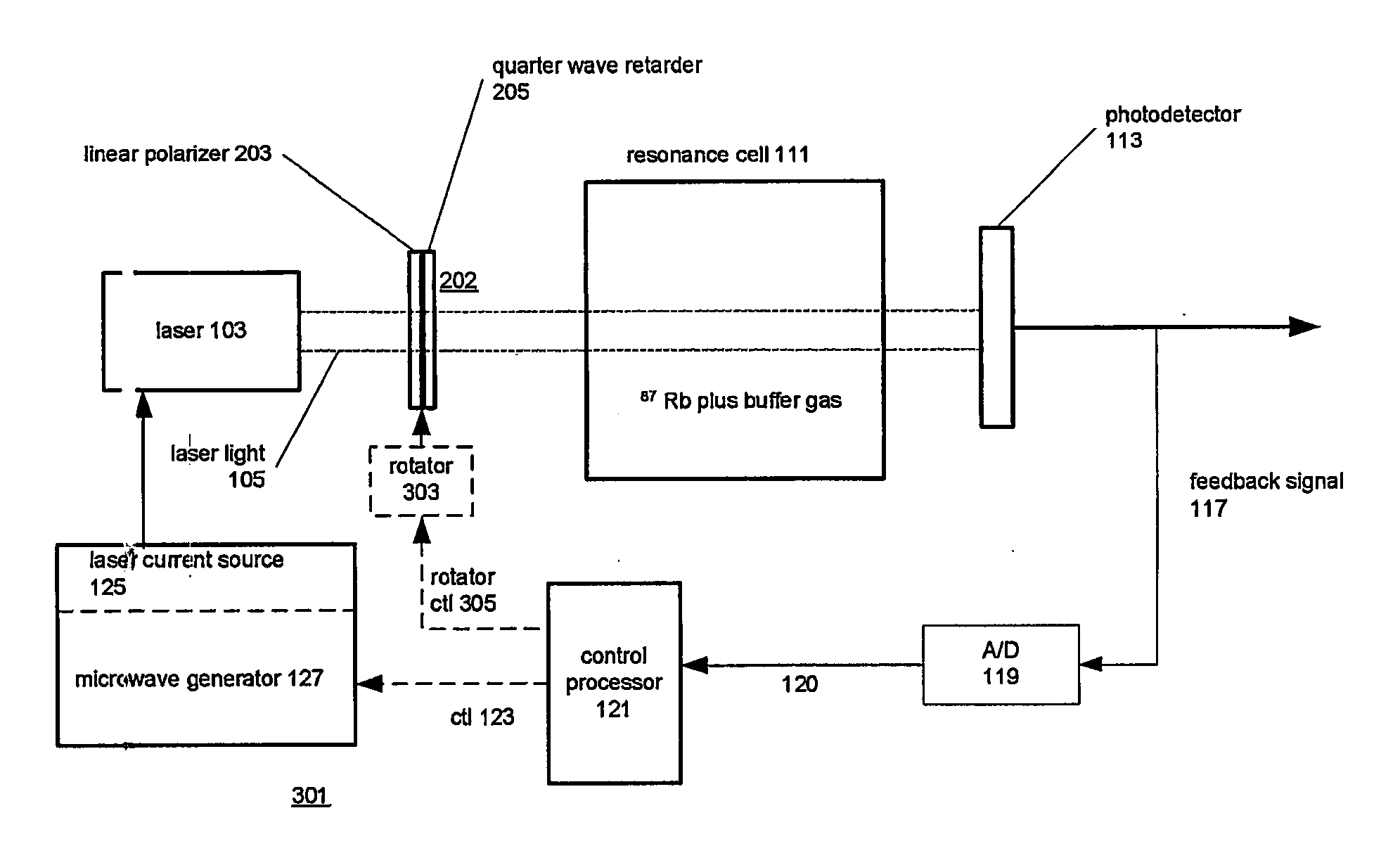
[0026] The following Detailed Description will describe a CPT frequency standard employing a rotatable circular polarizer to control the intensity of circularly-polarized light incident on the atomic resonance cell, and will finally disclose experimental results using a circular polarizer in this fashion in the CPT frequency standard.

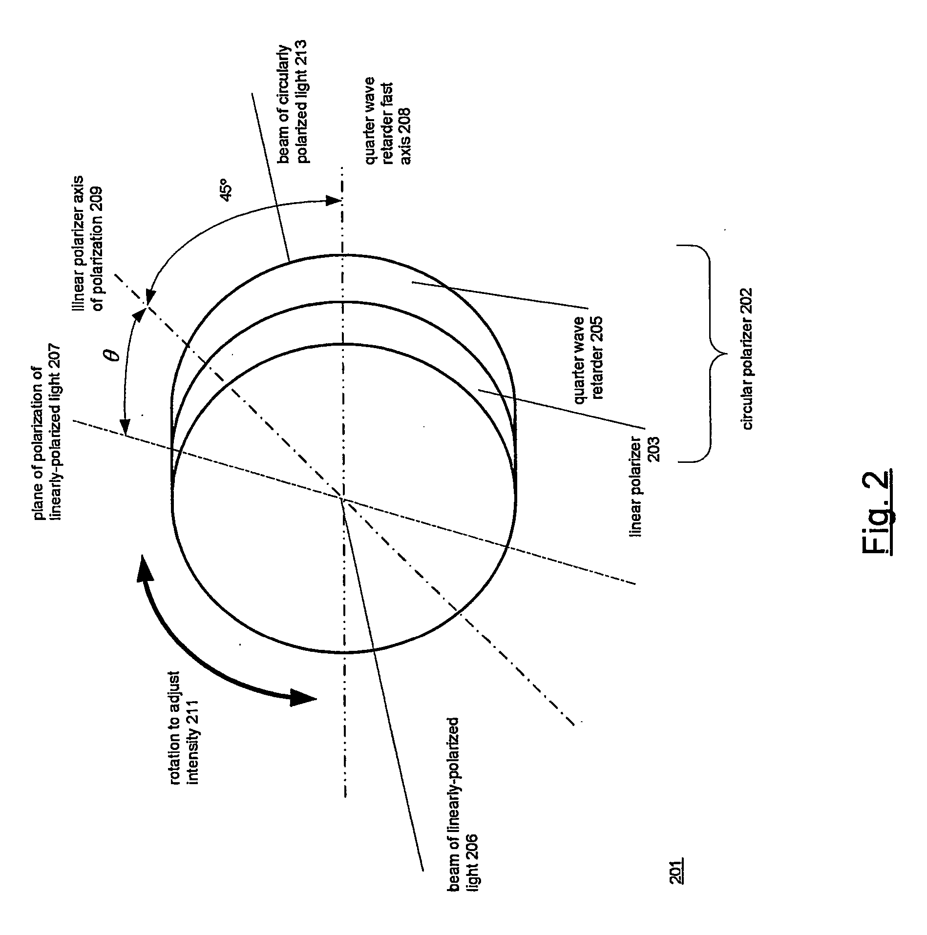
Using a Circular Polarizer to Control the Intensity of Circularly-Polarized Light: FIG. 2

[0027]FIG. 2 shows at 201 how a circular polarizer 202 may be used to control the intensity of circularly-polarized light. Circular polarizer 202 is made in the usual fashion: a linear polarizer 203 is combined with a quarter wave retarder 205 such that there is a fixed relationship between the axis of polarization 209 and the fast axis 208 of the quarter wave retarder. The linear polarizer and quarter wave retarder may be made of any materials which polarize light in the required fashions. A preferred relationship between the axis of polarization 209 and fast axi...


PUM


Abstract

An optically-excited atomic frequency standard that subjects alkali metal atoms (111) to circularly-polarized optical radiation. The atomic frequency standard is improved by the use of a circular polarizer (202) to control the intensity of the circularly-polarized optical radiation. The circular polarizer includes a linear polarizer (203) and a quarter-wave retarder (205), with the light to be circularly polarized passing first through the linear polarizer (203) and then through the quarter-wave retarder (205). In the atomic frequency standard, the optical radiation (105) to which the circular polarizer (202) is applied is itself linearly polarized, and the intensity of the circularly polarized light produced by the circular polarizer (202) is controlled by rotating (303) the circular polarizer. The degree of rotation determines how much of the linearly-polarized optical radiation passes through the linear polarizer, and thus how much circularly-polarized light is produced.

Description

CROSS REFERENCES TO RELATED APPLICATIONS [0001] The present patent application claims priority from U.S. Provisional Patent Application 60 / 525,340, Laiacano, et al, Apparatus for varying the amount of optical attenuation, filed Nov. 26, 2003. The subject matter of the present patent application is an improved coherent population trapping atomic frequency standard employing the an innovative technique for controlling the intensity of the circularly-polarized light required for operation of the frequency standard. A frequency standard of a type in which the improvement may be made is disclosed in detail in U.S. Pat. No. 6,320,472, Jacques Vanier, Atomic Frequency Standard, issued Nov. 20, 2001. That patent is incorporated by reference herein for all purposes.BACKGROUND OF THE INVENTION [0002] 1. Field of the Invention [0003] The invention relates generally to the field of atomic frequency standards and particularly to atomic frequency standards which are optically excited using a tech...

Claims


Application Information

Patent Timeline
Patent Type & Authority Applications(United States)
IPC IPC(8): G01J3/42G02BG04F5/14H01S1/06H03B17/00
CPCG04F5/14G04F5/145
Inventor LAIACANO, ADAMEVERSON, CAMERONLEVINE, MARTIN W.
Owner MICROSEMI FREQUENCY & TIME
Why Eureka
Try Eureka