
Heat dissipating apparatus for computer add-on cards

Inactive Publication Date: 2007-05-03
HON HAI PRECISION IND CO LTD
View PDF7 Cites 9 Cited by
  • Summary
  • Abstract
  • Description
  • Claims
  • Application Information

AI Technical Summary

Benefits of technology

[0005] Accordingly, what is needed is a heat dissipating apparatus which has an enlarged heat dissipating area and a more efficient means for removing heat therefrom so as to enhance heat dissipating efficiency.
[0006] According to a preferred embodiment of the present invention, a heat dissipating apparatus for use with an add-on card, such as a VGA card, comprises a base, a cover spaced from the base, a plurality of fins thermally connecting the cover and the base, a fan positioned on the base to blow air to the fins, and a heat pipe comprising an evaporating portion and a condensing portion. The evaporating portion is sandwiched between the base and the fins. The condensing portion between the fins and the cover. The cover absorbs heat from the fins and the condensing portion of the heat pipe. The fins and the cover dissipate heat to atmosphere immediately. Thus, the heat dissipating apparatus has an increased heat dissipating area and thereby enhancing hat dissipating efficiency.

Problems solved by technology

Electronic components such as central processing units (CPUs), thermoelectric elements, video graphics array (VGA) cards, and power transistors generate a large amount of heat during operation.
When the temperature of an electronic component exceeds a certain level, the electronic component may malfunction or outright fail in the worst case.
However, in a conventional manufacturing process, the heat dissipating fins of a conventional heat sink cannot be made thin enough to increase the heat dissipating efficiency.
In addition, the cost for manufacturing extremely thin fins by the conventional methods, i.e., metal extrusion or stamping, is high.
Although cool air is blown to the heat sink by the fan, most of the air cannot fully flow through the fins and is deflected away midways of heat dissipation fins of the heat sink, so that the cooling efficiency of the fan is not high.
Moreover, the mounting of the fan on the top of the heat sink makes a total height of the heat dissipation device be too large to be suitable for use in an environment which has a height limitation.

Method used


Image

  • Heat dissipating apparatus for computer add-on cards
  • Heat dissipating apparatus for computer add-on cards
  • Heat dissipating apparatus for computer add-on cards

Examples


Embodiment Construction

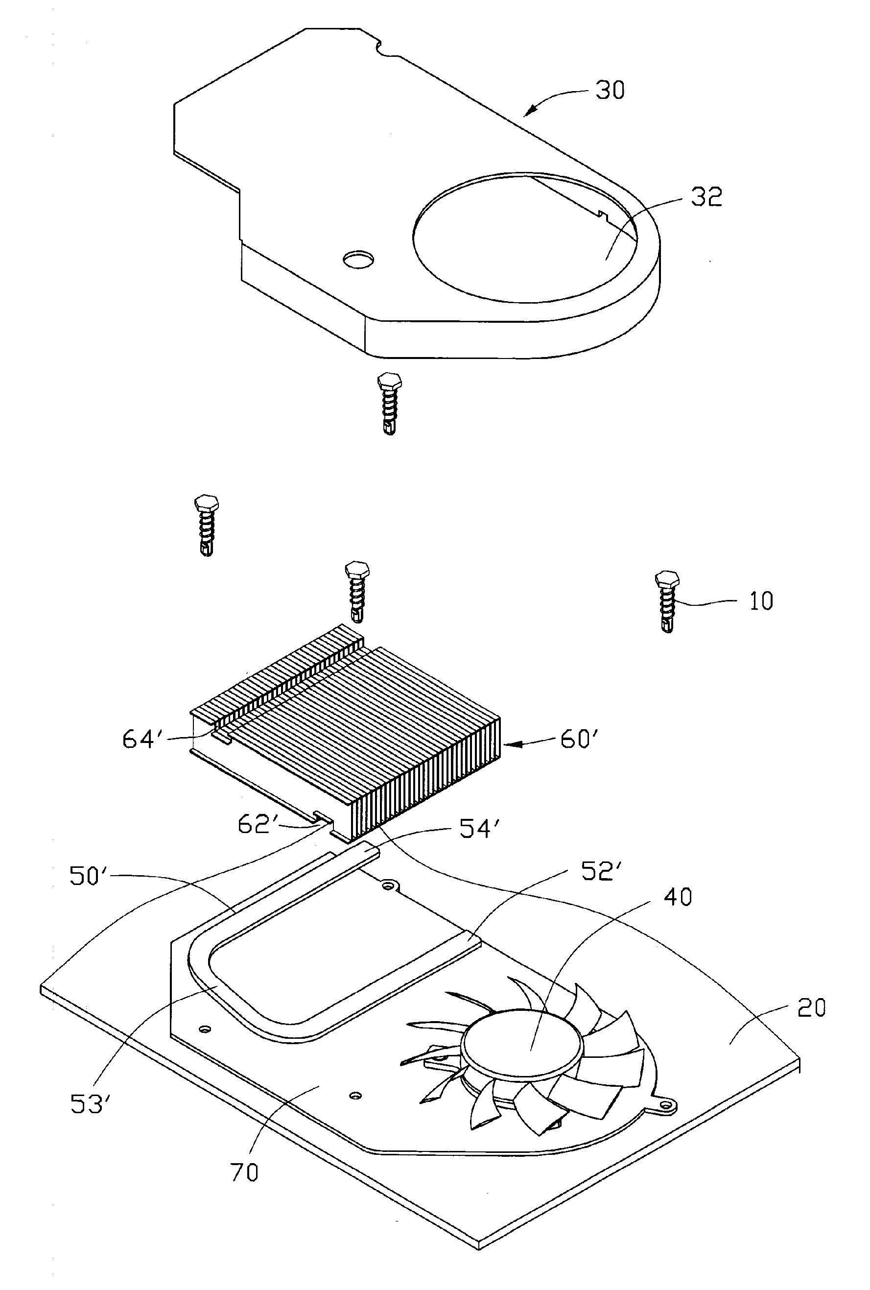
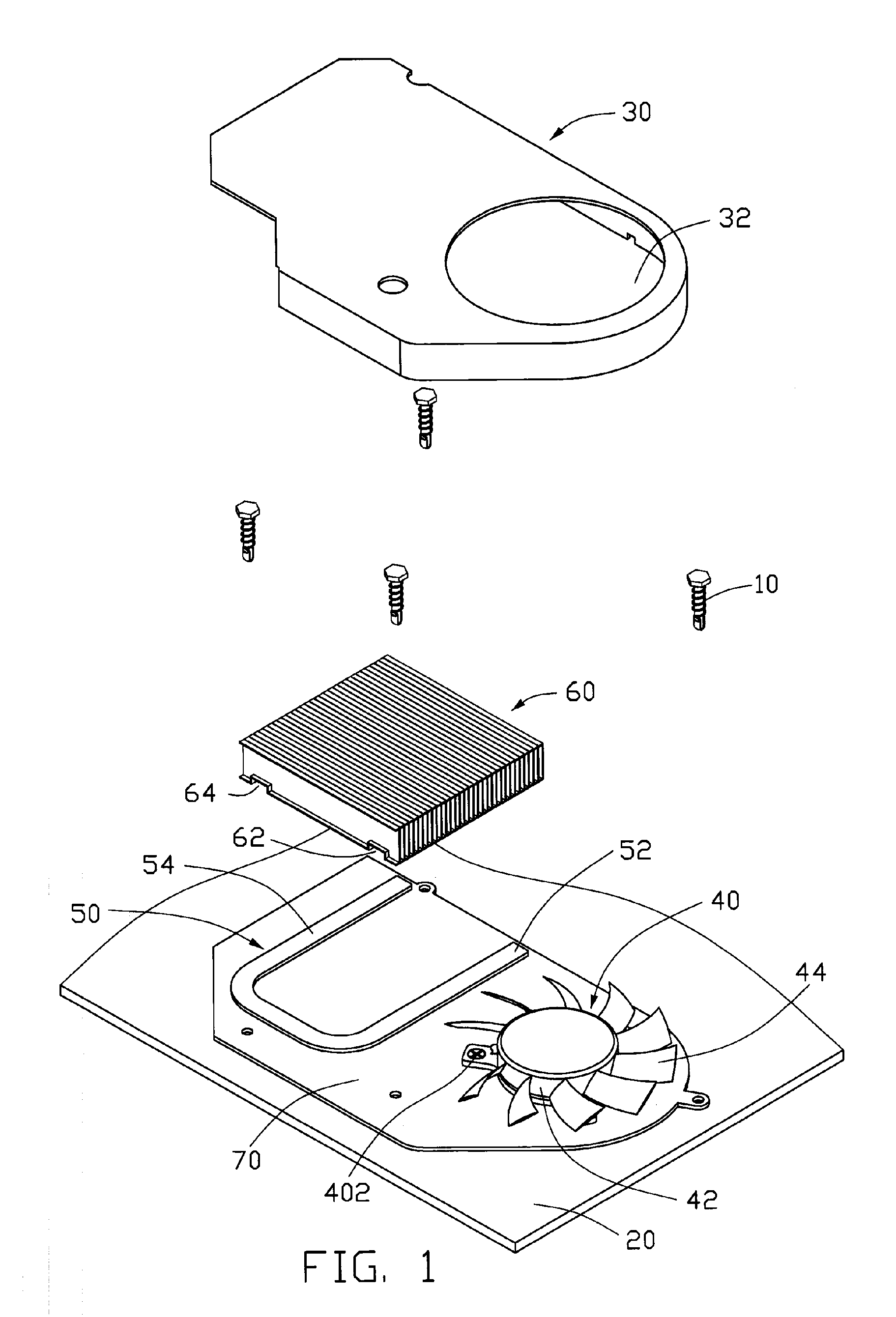
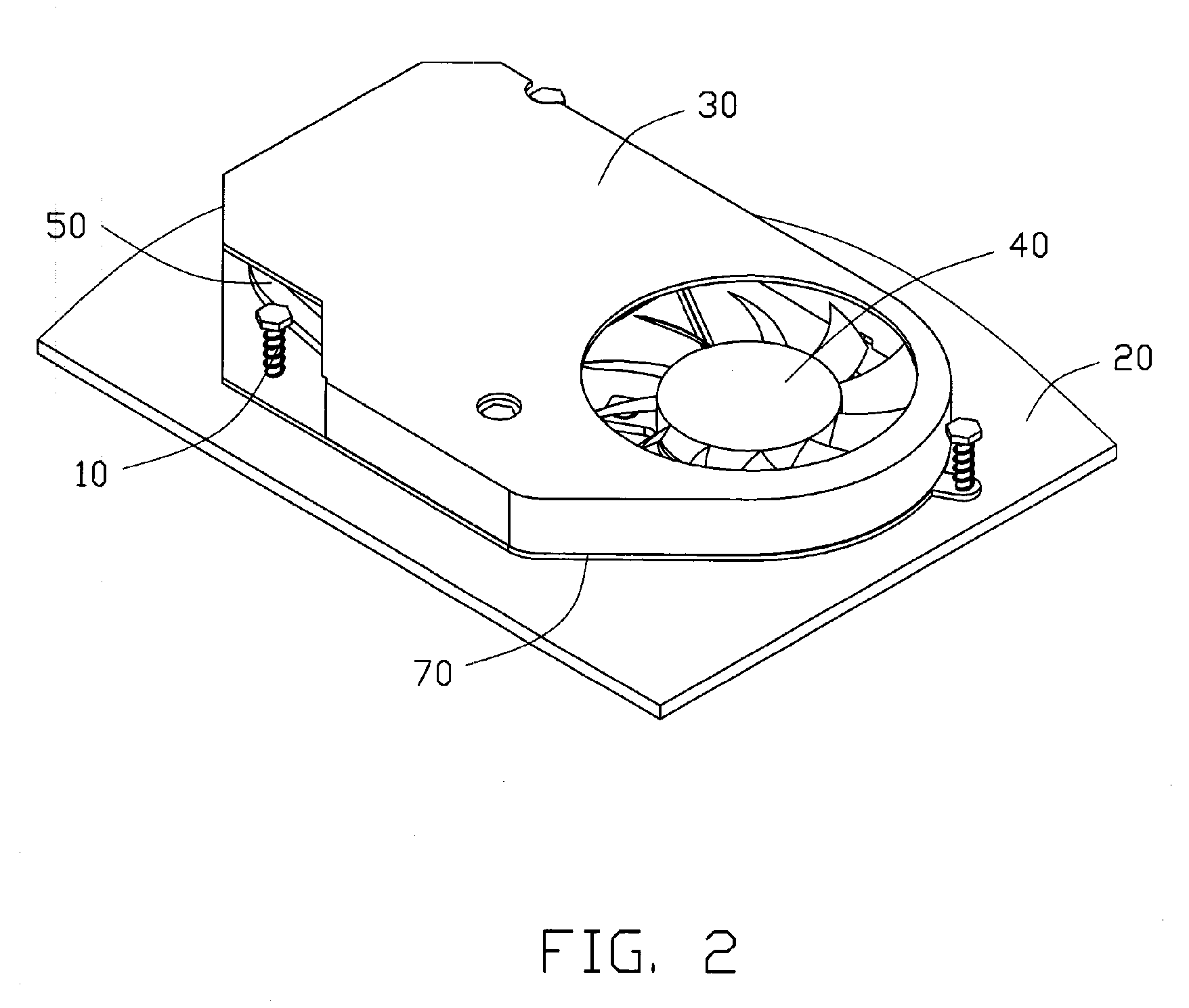
[0013]FIGS. 1-2 show a heat dissipating apparatus in accordance with a first preferred embodiment of the present invention. The heat dissipating apparatus mainly comprises a base 70, a plurality fins 60 soldered to the base 70, a heat pipe 50 positioned on the base 70 and extending through the fins 60, a fan 40 located on the base 70, and a cover 30 soldered onto the base 70 and covering the fins 60, the fan 40 and the heat pipe 50. The apparatus is mounted onto an add-on card 20 (such as a VGA card) for dissipating heat generated by a processor (not shown) of the add-on card 20 to achieve effective heat dissipation. For a VGA card, the processor is a GPU (graphic processing unit).

[0014] The base 70 is secured to the add-on card 20 by four suitable fasteners 10. Each fin 60 is a single metal piece, and defines first and second parallel rectangular slots 62, 64 at a bottom portion thereof.

[0015] The heat pipe 50 has a U-shaped configuration. The heat pipe 50 is flattened and has a ...


PUM


Abstract

A heat dissipating apparatus mounted onto an add-on card (20) includes a base (70), a cover (30) mounted on the base, a plurality of fins (60) received between and thermally connecting the cover and the base, a fan (40) positioned on the base to blow air to the fins, and a heat pipe (50) including an evaporating portion (52) and a condensing portion (54). The evaporating portion and condensing portion are sandwiched between the base and the fins. The cover absorbs heat from the fins and dissipates the heat to ambient air. Thus, the heat dissipating area is increased due to the cover, and the heat dissipating apparatus has a better heat dissipating efficiency.

Description

FIELD OF THE INVENTION [0001] The present invention relates to a heat dissipating apparatus for computer add-on cards and particularly a heat dissipating apparatus mounted onto a VGA (video graphic array) card for dissipating heat generated by the VGA card, wherein the heat dissipating apparatus has an increased heat dissipating area to thereby enhance heat dissipating efficiency. DESCRIPTION OF RELATED ART [0002] Heat sinks serve as cooling devices for heat generating objects such as electronic components or other electronic devices, by absorbing heat generated by such objects and dissipating the absorbed heat into ambient air. Electronic components such as central processing units (CPUs), thermoelectric elements, video graphics array (VGA) cards, and power transistors generate a large amount of heat during operation. When the temperature of an electronic component exceeds a certain level, the electronic component may malfunction or outright fail in the worst case. For this reason,...

Claims


Application Information

Patent Timeline
IPC IPC(8): H05K7/20
CPCH01L23/427H01L23/467H01L2924/0002H01L2924/00
Inventor PENG, XUE-WEN
Owner HON HAI PRECISION IND CO LTD
Features
  • Generate Ideas
  • Intellectual Property
  • Life Sciences
  • Materials
  • Tech Scout
  • Unparalleled Data Quality
  • Higher Quality Content
  • 60% Fewer Hallucinations
Learn More