Apparatus and method for image coding

a technology of image coding and apparatus, applied in the field of apparatus and method for image coding, can solve the problems of large computational volume, large visual degradation, and all kinds of mixed images that have had difficulty in optimally coding, and achieve the effects of less visual distortion, high speed coding processing, and small scal

Inactive Publication Date: 2007-05-03
KITAKYUSHU FOUND FOR THE ADVANCEMENT OF IND
View PDF1 Cites 11 Cited by
  • Summary
  • Abstract
  • Description
  • Claims
  • Application Information

AI Technical Summary

Benefits of technology

[0010] It is accordingly an object of the invention to provide an image coding technique capable of realizing a high speed coding processing for a mixed image with less of a visual distortion and further realizing a small scale circuit even if the coding is parallel processed on a hardware.

Problems solved by technology

With such a difference in nature of a pattern between the images based on attributes thereof, all kinds of mixed images have had difficulty in optimally encoding the mixed image by means of a conventional image coding scheme described above.
For example, in a case where a mixed image is encoded with JPEG, mosquito noise is generated in profiles of a letter or graphics in an artificial image portion, leading to a great visual degradation.
In the image coding scheme separating a mixed image into two regions: a discrete gray scale region mainly constituted of an artificial image and a continuous gray scale region mainly constituted of a natural image, however, a computational volume is great in operation of region division of an image, which makes it unsuitable for a high speed image compression.
In this case, however, a circuit scale is tremendously large.

Method used


Image

  • Apparatus and method for image coding
  • Apparatus and method for image coding
  • Apparatus and method for image coding

Examples


first embodiment

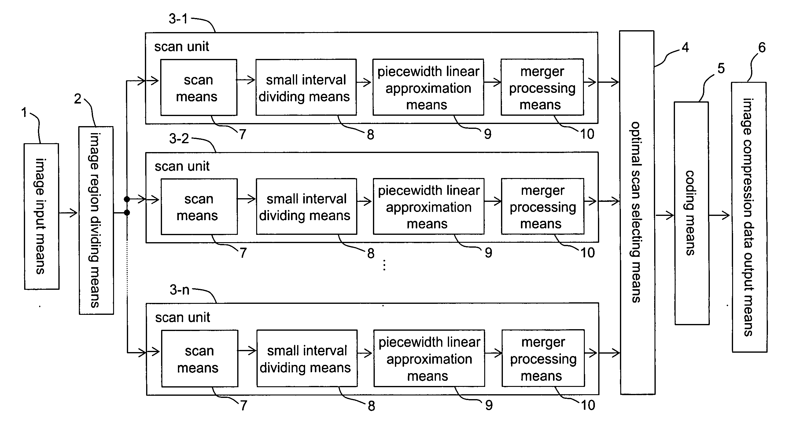
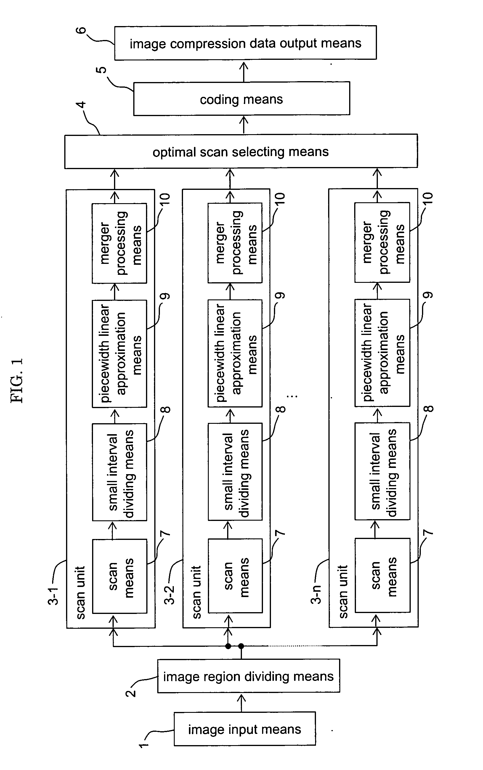
[0079]FIG. 1 is an overall construction diagram of an image coding apparatus concerning a first embodiment of the invention. In FIG. 1, the image coding apparatus concerning the first embodiment of the invention includes: an image input means 1; an image region dividing means 2; n (n≧2) scan units 3-1 to 3-n; an optimal scan selecting means 4; a coding means 5; and an image compression data output means 6.

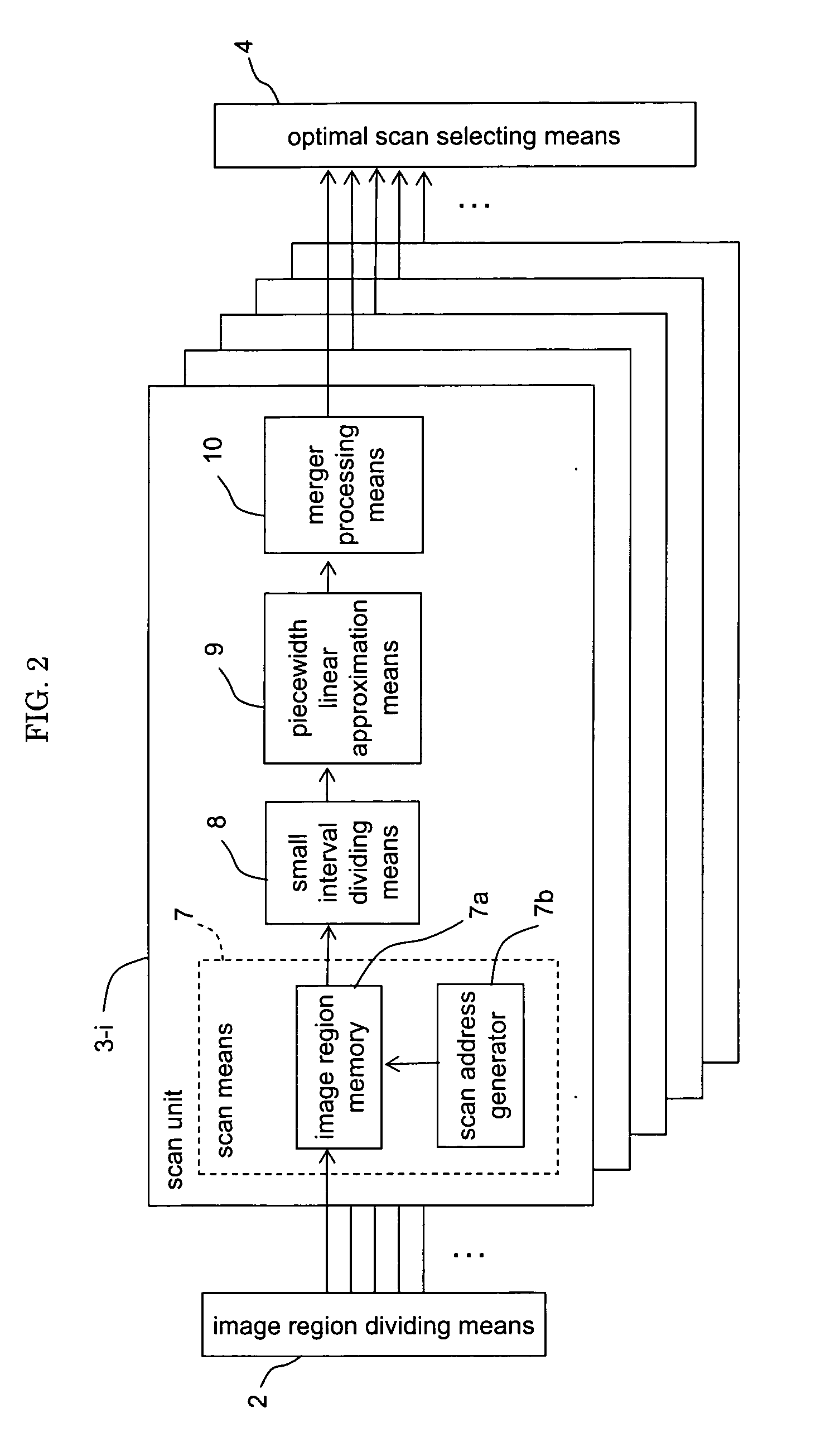
[0080] The image input means 1 inputs data of an original image to an image input apparatus. Examples of the image input means 1 include: an image pick-up device such as a CCD device; a television receiver; and image storage apparatus such as a magnetic disc apparatus. The image region dividing means 2 divides an image inputted from the image input means 1 into plural small regions (image blocks). The scan units 3-i (i=1, . . . , n) not only scan the image blocks divided by the image region dividing means 2 according to respective predetermined scan sequences, but also conduct pie...

second embodiment

[0153] In the first embodiment, the optimal scan selecting means 4 awaits, in step S5 of FIG. 8, till processing end signals are transmitted by all the scan units 3-1 to 3-n, whereas if processings by all the scan units 3-1 to 3-n awaits with one accord in this way, a processing time is determined by scanning according to a scan sequence requiring the longest time in piecewidth linear approximation processing, slowing a processing speed. On the other hand, a time requiring for piecewidth linear approximation processing is longer with a more number of intervals obtained by division in the processing.

[0154] Therefore, in step S5 of FIG. 8 of this embodiment, piece width linear approximation processing of scan units of which piecewidth linear approximation processing is not yet completed is terminated when piecewidth linear approximation processing of a prescribed number n1 of scan units is completed.

[0155]FIG. 18 is a block diagram showing an optimal scan selecting means 4′ of an im...

third embodiment

[0163] In this embodiment, when one scan unit 3-s completes piecewidth linear approximation processing and makes definite the number of intervals l(s) of the generated one-dimensional approximation image data, each of the other scan units forcibly terminates piecewidth linear approximation processing when the number of intervals li thereof at a time point is equal to or more than the reference number of intervals lst, wherein the definite number of intervals l(s) or a number l(s)+Δl obtained by adding a prescribed value to the definite number of intervals l(s) is adopted as the reference number of intervals lst.

[0164]FIG. 22 is a block diagram showing an optimal scan selecting means 4″ of an image coding apparatus concerning the third embodiment. FIG. 23 is a flow chart showing an image coding method concerning a third embodiment. FIG. 24 is a flowchart showing operations in an operation unit of the image coding apparatus concerning a third embodiment.

[0165] The optimal scan selec...


PUM


Abstract

Provided is an image coding technique capable of realizing a high speed coding processing for a mixed image with less of a visual distortion. The image coding apparatus includes: plural scan units 3 each having scan means 7 scanning an original image to be encoded according to a prescribed scan sequence and piecewidth linear approximation means 9 dividing a one-dimensional original image generated by scanning the original image with the scan means 7 into plural intervals so that accumulated square error or a dispersion of pixel values in each interval is a prescribed threshold value or less to generate one-dimensional approximation image data obtained by approximation of pixel values by the average value of pixel values in the intervals, which correspond to each of plural scan sequences different from one another; and optimal scan selecting means 4 comparing the numbers of intervals obtained by dividing of the piecewidth linear approximation means 9 of the scan units 3 to thereby select one dimensional approximation image data having a minimum number of intervals.

Description

BACKGROUND OF THE INVENTION [0001] 1. Field of the Invention [0002] The invention relates to an image coding technique used in compression, transmission or the like of an image, and in particular, to an image coding technique capable of optimally encoding a mixed image in which an artificial image and a natural image are mixed. [0003] 2. Description of the Related Art [0004] A mixed image is an image in which a natural image such as a photograph and an artificial image such as a letter, graphics or illustrations coexist. As techniques for non-reversible compression of a mixed image, there have conventionally been widely employed various kinds of coding schemes such as JPEG, GIF, and TIFF. [0005] An original image to be encoded is different in nature of a pattern therein according to whether the original image is a natural image or an artificial image. In a natural image, there is a large correlation between pixels and a continuous change in pixel value. On the other hand, an artific...

Claims


Application Information

Patent Timeline
Patent Type & Authority Applications(United States)
IPC IPC(8): G06K9/36
CPCH04N19/129H04N19/60H04N19/436H04N19/17H04N19/27H04N19/152
Inventor KAMATA, SEIICHIRO
Owner KITAKYUSHU FOUND FOR THE ADVANCEMENT OF IND
Why Eureka
Try Eureka