Configuration management system and method for use in an RFID system including a multiplicity of RFID readers

a technology of configuration management system and rfid reader, which is applied in the direction of burglar alarm mechanical actuation, instruments, wireless communication, etc., can solve the problems of difficult to determine reliably the direction of travel of the tagged item, the operation of the conventional rfid system is problematic, and the effect of increasing the efficiency of the rfid system

Inactive Publication Date: 2007-05-03
TELEFON AB LM ERICSSON (PUBL) +2
View PDF26 Cites 66 Cited by
  • Summary
  • Abstract
  • Description
  • Claims
  • Application Information

AI Technical Summary

Benefits of technology

[0015] In accordance with the present invention, a system and method is provided that manages the configuration and control of components of a radio frequency identification (RFID) system, taking into account how the RFID system components are associated with one or more physical locations within an environment in which the RFID system is deployed. The presently disclosed system and method allows the associations between the system components and the physical locations to be specified in a dynamic fashion based primarily upon how the various components are used within the system environment. The presently disclosed system and method also allows logical and physical relationships between the system components and the physical locations to be determined in accordance with how the components and locations are associated with one another. In addition, by permitting properties to be assigned to both the system components and the physical locations, while presenting an enhanced visual representation of how the components and locations exist within the system environment, the presently disclosed system and method provides for more cooperative information gathering among the various system components, and more meaningful decision making based upon the acquired information, thereby allowing the business purpose of the RFID system to be more easily attained.
[0016] In one embodiment, the presently disclosed system and method is configured to operate in conjunction with an RFID system architecture that includes a plurality of RFID transponders or tags, a plurality of RFID readers, at least one host computer running at least one client software application, and at least one mid-level controller / processor in communication with the plurality of RFID readers and the host computer. Within the RFID system architecture, each of the RFID readers includes an RF interrogator and an RF receiver, which may reside in separate units or may be integrated into a single component or device. The mid-level controller / processor is operative to schedule, parameterize, and coordinate RF transmissions generated by the respective RFID readers, to receive tag data from the RFID readers, and to provide raw tag data, processed tag data, RFID reader location information, event information, and / or system status notifications to the host computer. In addition, the mid-level controller / processor is operative to exchange RFID reader control signaling with both the host computer and the RFID readers to provide coordinated control of the multiple readers. By employing the presently disclosed system and method to manage the configuration and control of the RFID readers via the mid-level controller / processor, enhanced RFID tag management functions, higher RFID tag read throughput, improved RF spectrum management, and increased cooperation among the various system components can be achieved.
[0021] Using the graphical user interface, the user may generate a composite of the facility view, the RF coverage view, and the location view to obtain a visual understanding of how the system components and the physical locations exist within the system environment, and how the components and locations are associated with one another. For example, the user may employ the composite of the multiple views to visualize the associations between the RF interrogation zones of the antennas and the specified physical locations within the system environment. The RF interrogation zones indicate those areas within the system environment where RFID tags are likely to be detected by an RF receiver, and the specified physical locations are indicative of the information required by the user, e.g., information relating to shipping, receiving, etc. The overlapping regions of the RF interrogation zones and the specified physical locations, as shown in the composite of the facility, coverage, and location views, indicate those areas within the system environment in which RFID tag interrogations by an RF interrogator will likely provide information pertinent to the user's requirements. Because interrogations of RFID tags outside of the overlapping regions of the interrogation zones and the physical locations are unlikely to provide pertinent user information, interrogations of tags in those areas can be limited or avoided altogether to increase the efficiency of the RFID system.
[0022] By allowing information to be entered regarding associations between components of an RFID system and specified physical locations within an environment in which the RFID system is deployed, providing a visual indication of the resulting configuration data from a facility view, an RF coverage view, and a location view of the data, and permitting properties to be assigned to the system components and physical locations with a visual understanding of how the components and locations exist within the system environment, the presently disclosed system and method provides for more cooperative information gathering among the various system components, and more meaningful decision making based upon the acquired information, thereby allowing the business purpose of the RFID system to be more easily attained.

Problems solved by technology

However, conventional RFID systems like those described above have drawbacks.
The operation of such a conventional RFID system can be problematic, however, because various factors such as multi-path propagation, RFID tag orientation, shadowing by an obstruction, etc., may prohibit the two RFID readers from successfully interrogating the tagged item at particular angles of interrogation.
For example, if the RFID readers are placed too close together within the system environment, then the order in which the readers detect the tagged item within their respective fields of view may vary, thereby making it difficult to determine reliably the direction of travel of the tagged item.
Further, one of the RFID readers may fail to detect the tagged item altogether, thereby making it virtually impossible to determine the item's direction of travel.
Moreover, interference between the two RFID readers may prohibit the readers from successfully interrogating the tagged item.
Such reader-to-reader interference may also prevent the two RFID readers from occupying the same frequency channel in the same time slot within a particular RF domain, resulting in significant degradation in the efficiency of the distributed sensor network.
However, in conventional RFID system configurations, there is no easy way of tying the named system components to the physical locations corresponding to those functions indicated by the named designations.
Conventional RFID system configurations are generally incapable of incorporating any formal understanding of how groups of system components relate to the physical space in which they are employed.
Further complications can result if a system component (e.g., an RF interrogator, an RF receiver, and / or an RFID reader) can be used to perform more than one function.
However, conventional RFID systems typically provide no way of unambiguously distinguishing between the interrogation zones corresponding to the shipping functions, and the interrogation zones corresponding to the receiving functions.
As a result, when one of the system components can be used for both shipping and receiving, it is difficult to determine whether interrogations performed by that component are associated with the shipping or receiving functions, especially when the component interrogates tagged items located within the overlapping region of the two interrogation zones.
However, as discussed above, in conventional RFID systems, there is no easy way of tying the system components to the physical locations within the system environment, whether those locations are permanent or merely temporary.

Method used


Image

  • Configuration management system and method for use in an RFID system including a multiplicity of RFID readers
  • Configuration management system and method for use in an RFID system including a multiplicity of RFID readers
  • Configuration management system and method for use in an RFID system including a multiplicity of RFID readers

Examples


Embodiment Construction

[0032] U.S. Provisional Patent Application No. 60 / 727,453 filed Oct. 17, 2005 entitled CONFIGURATION MANAGEMENT SYSTEM AND METHOD FOR USE IN AN RFID SYSTEM INCLUDING A MULTIPLICITY OF RFID READERS is incorporated herein by reference.

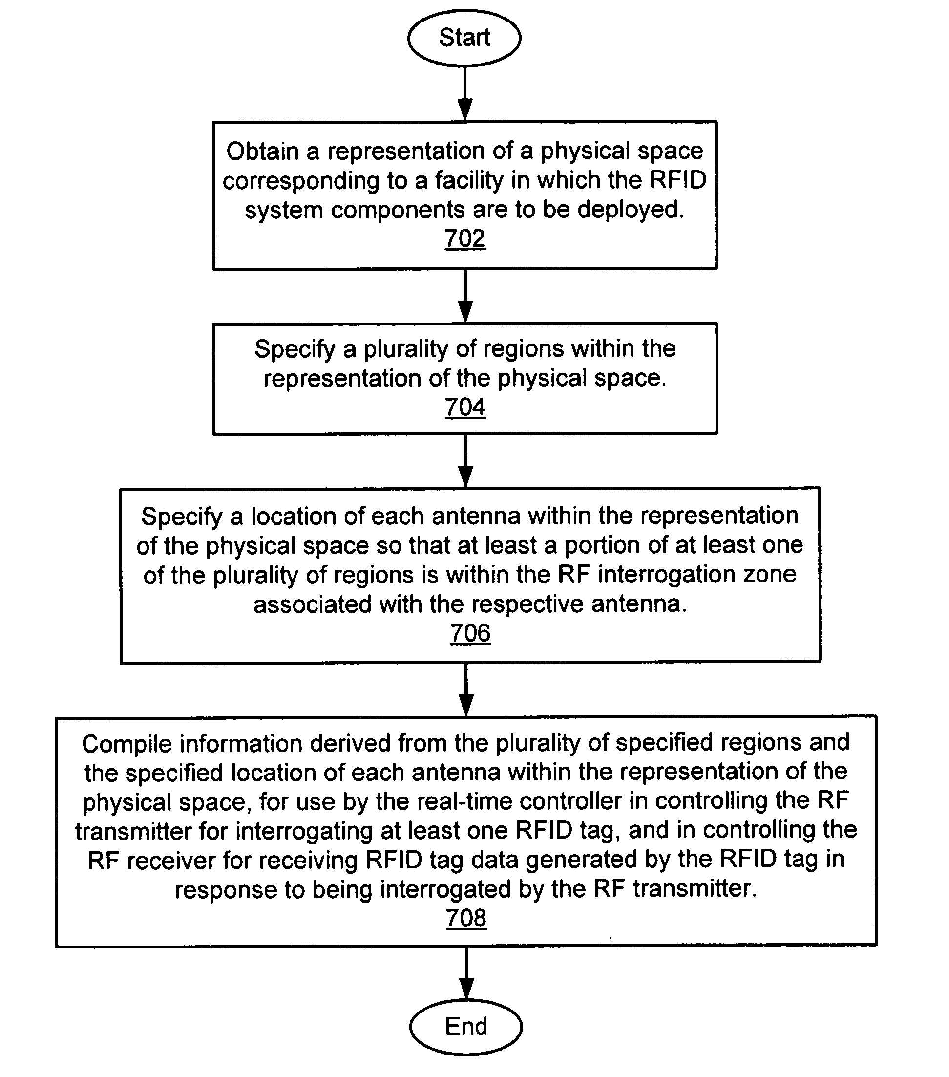
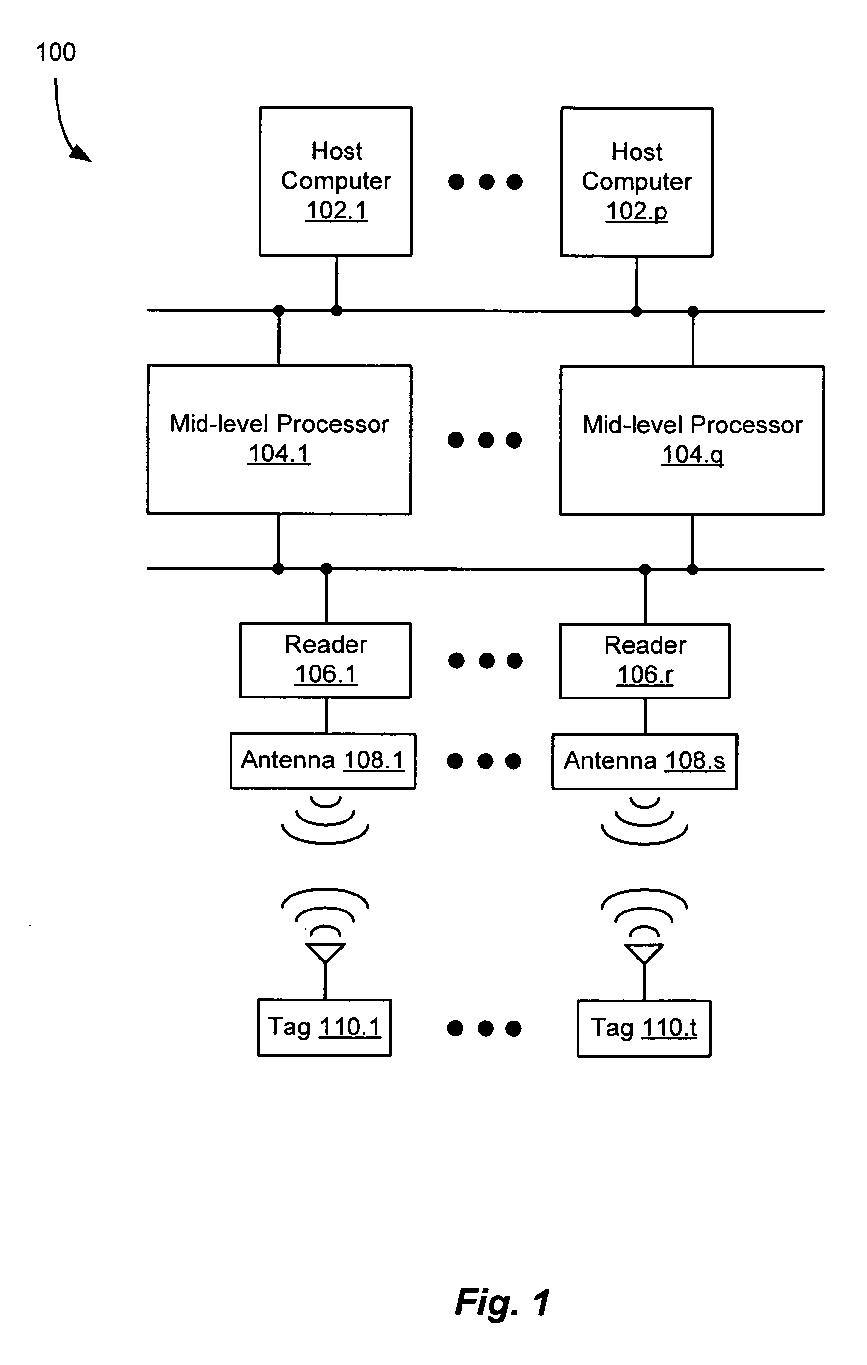
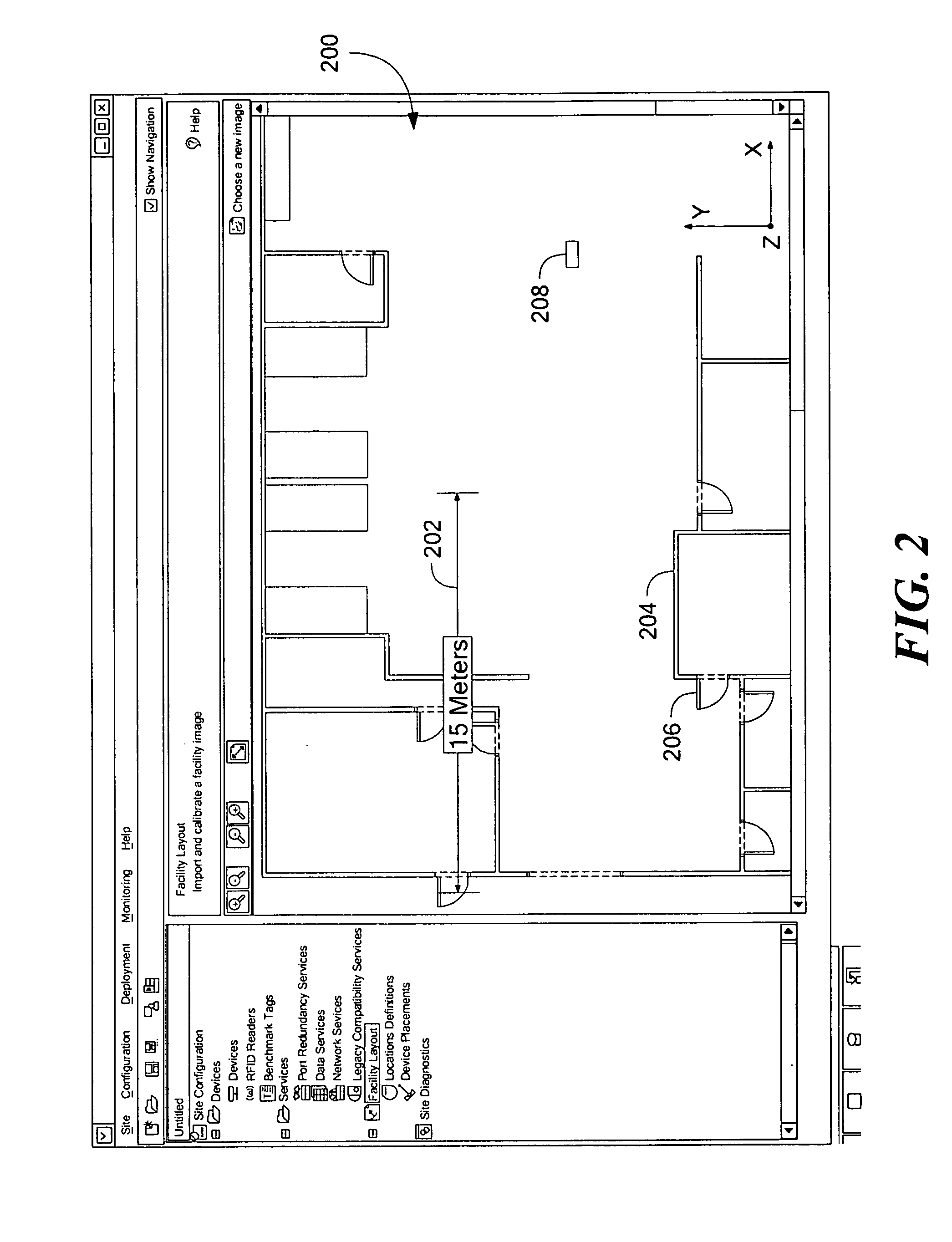
[0033] A system and method is provided that manages the configuration and control of components of a radio frequency identification (RFID) system, taking into account how the RFID system components are associated with one or more physical locations within an environment in which the RFID system is deployed. The presently disclosed system allows associations between the system components and the physical locations to be specified in a dynamic fashion based primarily upon how the various components are used within the system environment. In addition, the presently disclosed system allows logical and physical relationships between the system components and the physical locations to be determined in accordance with how the components and locations are assoc...


PUM


Abstract

A system and method that facilitates the configuration and control of components of an RFID system, taking into account how the RFID system components are associated with one or more physical locations within an environment in which the RFID system is deployed. A user provides information specifying associations between the system components and the physical locations within the environment to obtain visual representations of configuration data generated therefrom with reference to a facility view, an RF coverage view, and a location view of the data. The facility view serves as a reference plane for placement and orientation of antennas associated with RFID readers, location benchmark tags, and the physical locations of interest. After each antenna is placed and oriented on the facility view, an estimate of the size and shape of the RF interrogation zone of each antenna is computed, and representations of the RF interrogation zones are provided on the facility view to obtain the RF coverage view of the data. Next, the user provides information specifying the physical locations of interest to obtain the location view of the data. A composite of the facility view, the coverage view, and the location view is then generated to obtain an enhanced visual understanding of how the system components and the physical locations exist within the system environment, and how the components and locations are associated with one another.

Description

CROSS REFERENCE TO RELATED APPLICATIONS [0001] This application claims benefit of U.S. Provisional Patent Application No. 60 / 727,453 filed Oct. 17, 2005 entitled CONFIGURATION MANAGEMENT SYSTEM AND METHOD FOR USE IN AN RFID SYSTEM INCLUDING A MULTIPLICITY OF RFID READERS.STATEMENT REGARDING FEDERALLY SPONSORED RESEARCH OR DEVELOPMENT [0002] Not applicable BACKGROUND OF THE INVENTION [0003] The present invention relates generally to radio frequency identification (RFID) systems, and more specifically to a system and method of managing the configuration and control of components of an RFID system, taking into account how the RFID system components are associated with one or more physical locations within an environment in which the RFID system is deployed. [0004] In recent years, radio frequency identification (RFID) systems have been employed in an ever increasing range of applications. For example, RFID systems have been employed in supply chain management applications to identify a...

Claims


Application Information

Patent Timeline
Patent Type & Authority Applications(United States)
IPC IPC(8): H04Q7/20G08B13/14H04W4/02H04W64/00H04W84/18
CPCH04W4/02H04W16/18H04W84/18H04L67/18H04L67/52
Inventor STEPHENSEN, ROBERT A.GRADY, MICHAELBARVICK, SCOTTHUSAK, DAVID J.ZHOU, LINSHAH, NIRAV R.KRISHNA, PATTABHIRAMANFISCHER, JEFFREY H.CABOT, CHILTON L.
Owner TELEFON AB LM ERICSSON (PUBL)
Why Eureka
Try Eureka