Apparatus, system, and method for controlling a desired torque output

a technology of torque output and transmission, applied in the direction of fluid couplings, gearings, couplings, etc., can solve the problems of force (torque) control, affecting the smooth speed transition of hydromechanical powertrains, and no known success in the earth-moving industry

Active Publication Date: 2007-05-10
CATERPILLAR INC
View PDF19 Cites 52 Cited by
  • Summary
  • Abstract
  • Description
  • Claims
  • Application Information

AI Technical Summary

Benefits of technology

[0007] In one aspect, an apparatus for controlling a desired torque output from a hydromechanical transmission. The apparatus comprises a control module configured to d

Problems solved by technology

Industry has had a measure of success with speed control systems in the agricultural industry but no known successes in the earth-moving industry.
The lack of force (torque) control put the earth-working machines with hydromechanical powertrains at a disadvantage when compared to conventional powertrains, particularly when the machine was pushing against massive objects, or digging.
Similarly, it was found that because earth-working machines are often employed on rapidly changing surface conditions and compromised stability, it was inherently harder to make smooth speed transitions with the traditional speed contr

Method used


Image

  • Apparatus, system, and method for controlling a desired torque output
  • Apparatus, system, and method for controlling a desired torque output
  • Apparatus, system, and method for controlling a desired torque output

Examples


Embodiment Construction

[0018] Reference will now be made in detail to embodiments of the invention, examples of which are illustrated in the accompanying drawing.

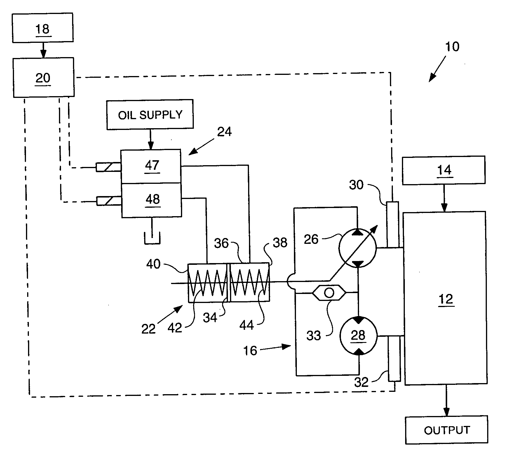
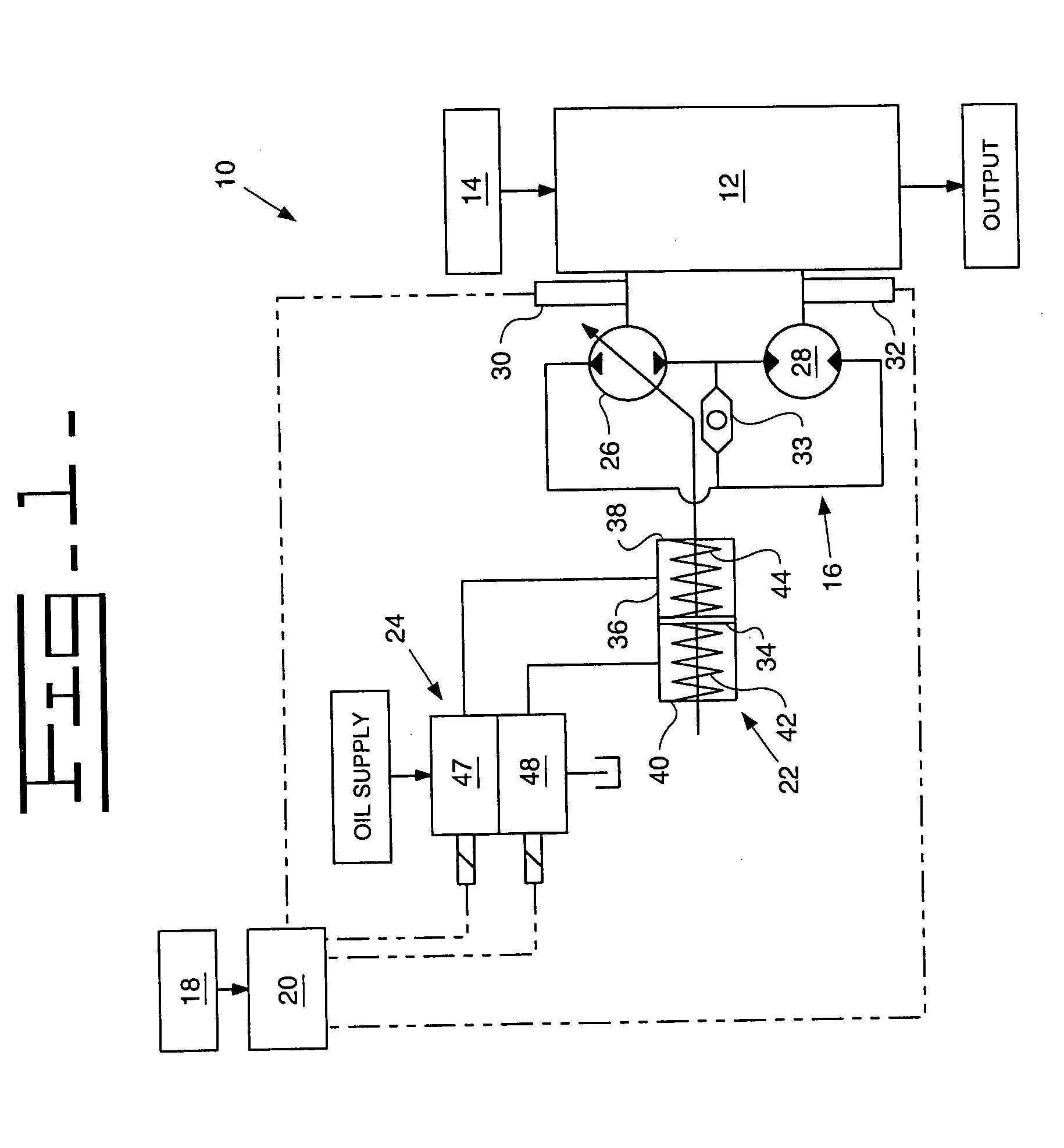
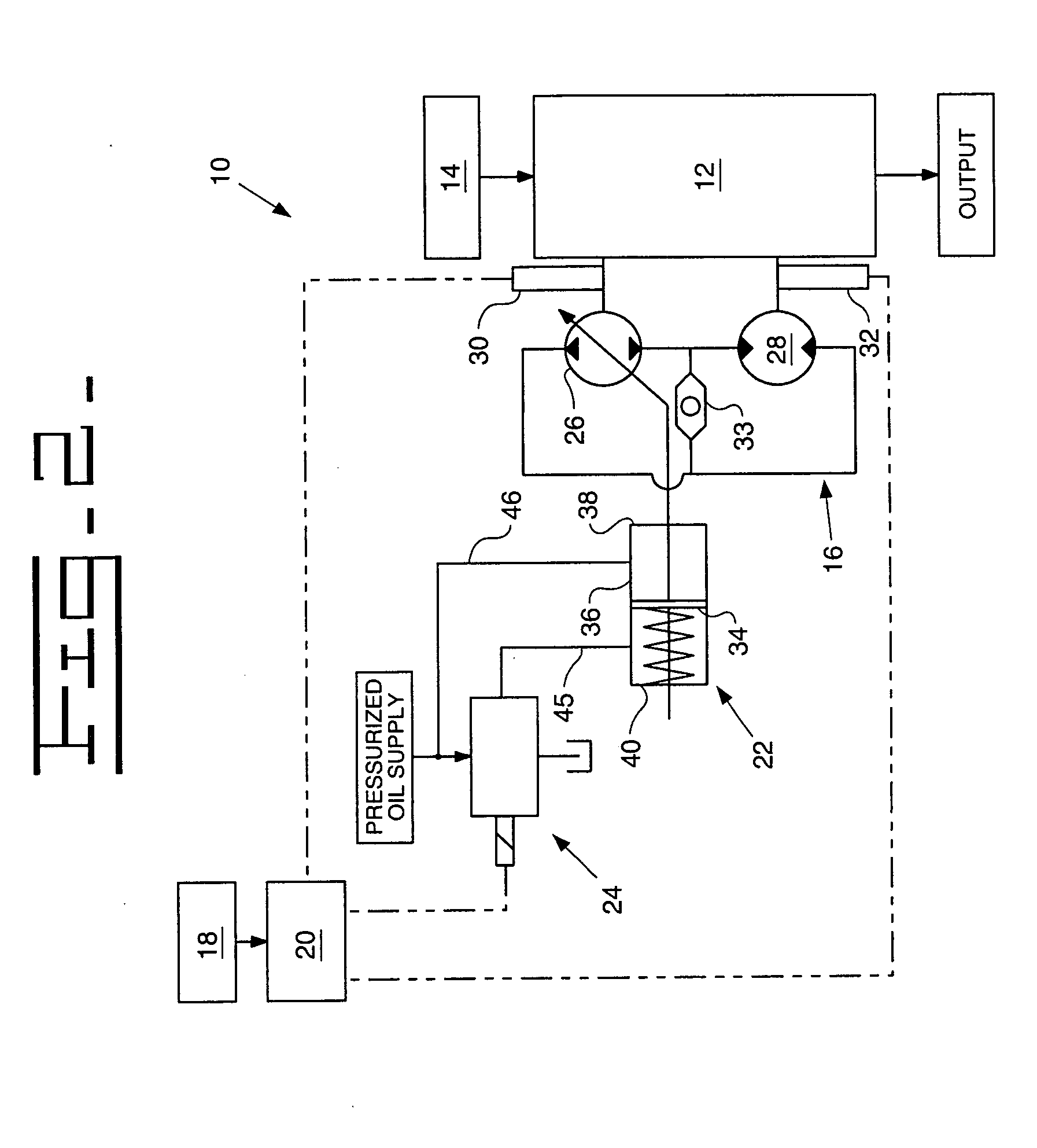
[0019] Referring to FIG. 1, a schematic for controlling torque output from a hydromechanical transmission 10 is shown. The hydromechanical transmission 10 comprises a gear system 12, a hydrostatic unit 16, an input module 18, a control module 20, an actuator 22, and a valve system 24.

[0020] The gear system, such as a transmission, 12 typically outputs to a traction device (not shown) on an earth-working machine. The traction device may include wheels located on each side of the earth-working machine. Alternatively, the traction device may include tracks, belts, or other driven traction implements. Preferably, an internal arrangement of the gear system 12 is a power split, a hydromechanical arrangement of the input coupled type, or a variable unit driven solely by an input, with one or more shiftable ranges. Other arrangements, such as output an...


PUM


Abstract

Apparatus, system, and method for controlling a desired torque output on a hydromechanical transmission. Controlling torque output of a hydromechanical transmission provides improved operator feel and control. A control module determines a desired torque output and determines a pressure necessary to influence the displacement of the variable displacement pump to output the desired torque output. A pressure-controlling valve applies that amount of pressure to an actuator, which moves in response thereto, to change the displacement of the variable displacement pump. When the motor speed changes, the control module adjusts the pressure applied to the actuator to provide the desired torque output.

Description

TECHNICAL FIELD [0001] The present invention relates to transmission controls, and more specifically to controlling a desired torque output from a hydromechanical transmission. BACKGROUND [0002] Hydromechanical, split torque, or parallel path powertrains provide many advantages over the typical mechanical transmissions used in earth-working machines, such as tractors, bulldozers, and wheel loaders. Specifically, hydromechanical transmissions provide continuous speed control, control of acceleration and deceleration, and management of engine speed with fewer losses. [0003] Current industry practice with hydromechanical transmissions is to control speed by controlling pump displacement. This practice requires a servo-feedback control on a pump actuator to force the pump actuator to a specific position. Industry has had a measure of success with speed control systems in the agricultural industry but no known successes in the earth-moving industry. The lack of force (torque) control put...

Claims


Application Information

Patent Timeline
IPC IPC(8): F16D31/02F16H61/42F16H61/433F16H61/46F16H61/472
CPCF16H47/02F16H59/42F16H61/433F16H61/46F16H61/472
Inventor CRONIN, MICHAEL G.
Owner CATERPILLAR INC
Why Eureka
Try Eureka