Aircraft engine nacelle ice protection system

a technology of nacelle and airframe, which is applied in the direction of machines/engines, mechanical equipment, transportation and packaging, etc., can solve the problems of increasing drag, constricting air flow into the engine, adversely affecting air flow patterns, etc., and achieves the effect of optimizing power consumption

Active Publication Date: 2007-05-10
THE BF GOODRICH CO
View PDF13 Cites 29 Cited by
  • Summary
  • Abstract
  • Description
  • Claims
  • Application Information

AI Technical Summary

Benefits of technology

[0004] The present invention provides a nacelle inlet lip ice protection system which preserves desired airflow patterns (into and around the engine), controls the size of ice particles shed, and optimizes power consumption. The ice protection system can utilize electrical energy to prevent / remove ice whereby problems associated with conventional bleed air heating (i.e., elevated temperature operation, thermal expansion accommodations, structural integrity considerations, pressure relief door requirements, engine efficiency compromises, etc.) are eliminated. Additionally, the ice protection system of the present invention can be used in conjunction with noise abatement constructions, such as those shown in US 2005 / 0006529.
[0005] More particularly, the present invention provides a nacelle inlet lip for an aircraft engine comprising a structural body and an ice protection system. The structural body defines the leading edge of the aircraft engine and has an inner wall portion defining the inlet for the aircraft engine. The inner wall portion has a plurality of inner zones located sequentially aft from the leading edge (e.g., an inner aft zone, an inner mid zone, and an inner aft zone) and the ice protection system has an ice-protector associated with each of the inner zones. Each ice-protector is independently controllable to allow the inner zones to be operated in different modes, different power levels, and / or different time intervals.

Problems solved by technology

Ice build-up on the lip can change the contour of the engine's air inlet, thereby adversely affecting air flow patterns (e.g., constricting air flow into the engine) and aerodynamic characteristics (e.g., increasing drag).
Moreover, if large pieces of ice break free from the inlet lip and enter the engine, they can damage rotor blades and other internal engine components.

Method used


Image

  • Aircraft engine nacelle ice protection system
  • Aircraft engine nacelle ice protection system
  • Aircraft engine nacelle ice protection system

Examples


Embodiment Construction

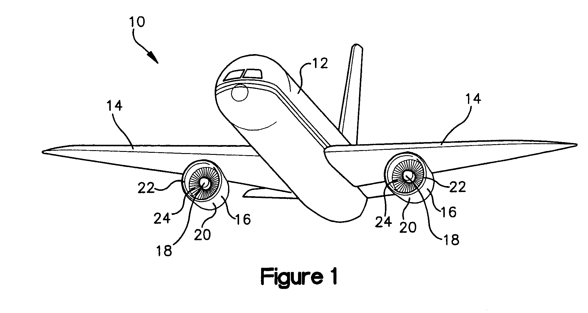
[0013] Referring now to the drawings, and initially to FIG. 1, an aircraft 10 is shown. The aircraft 10 comprises fuselage 12, wings 14, and engines 16. Each engine 16 comprises internal engine components 18 (e.g., turbofan components) and a nacelle 20 which houses the internal engine components 18. Each nacelle 20 includes an inlet lip 22 which defines the inlet opening 24 through which air enters the engine 16. In the illustrated aircraft 10, the engines 16 are mounted to the wings 14 and the nacelles 20 would probably be considered relatively large in the aircraft industry (e.g., they each have a diameter that exceeds ten feet). However, the engines 16 could additionally or alternatively be mounted in other aircraft locations, and / or the engines 16 and / or nacelles 20 could be of a variety of sizes.

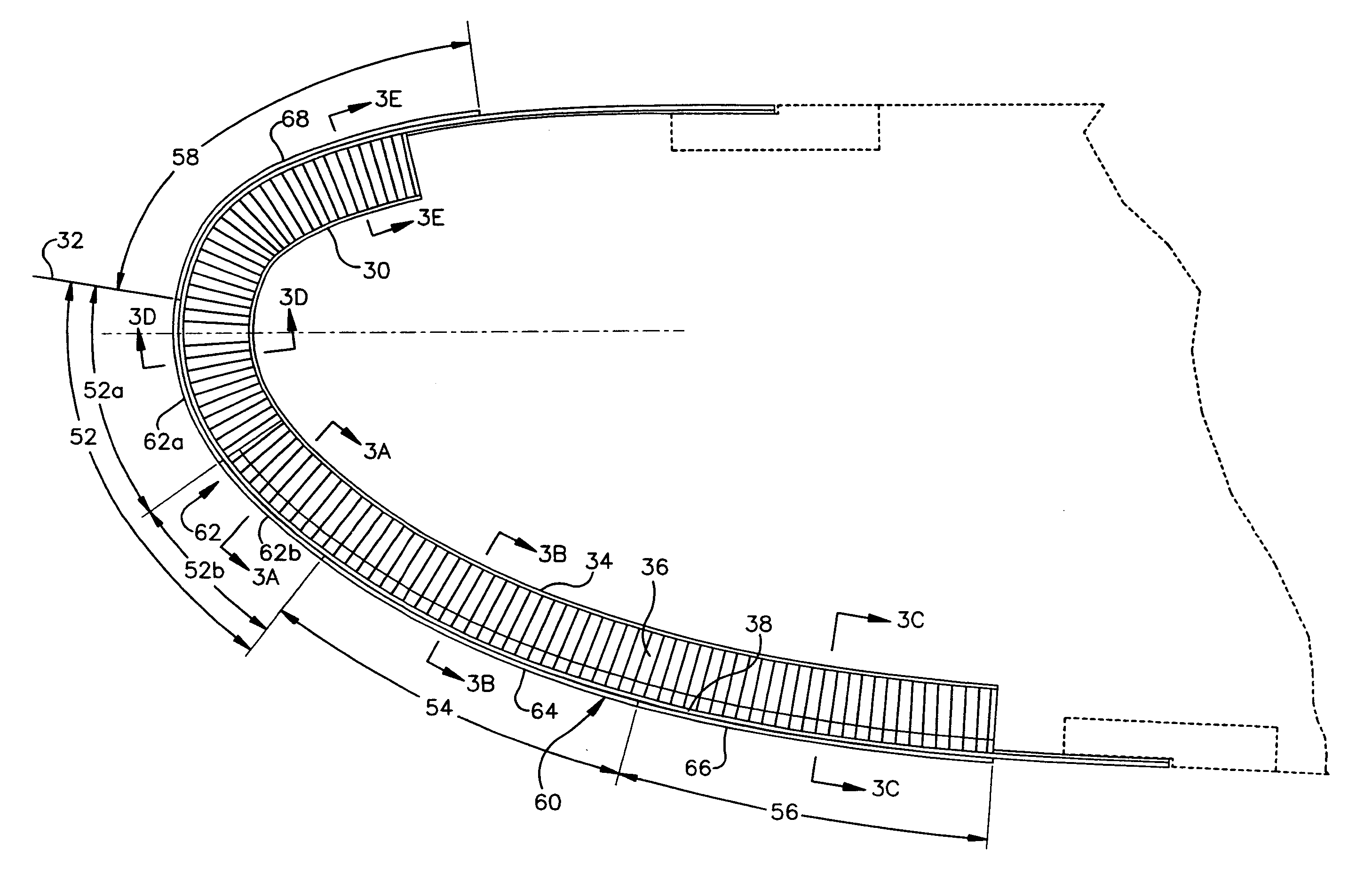
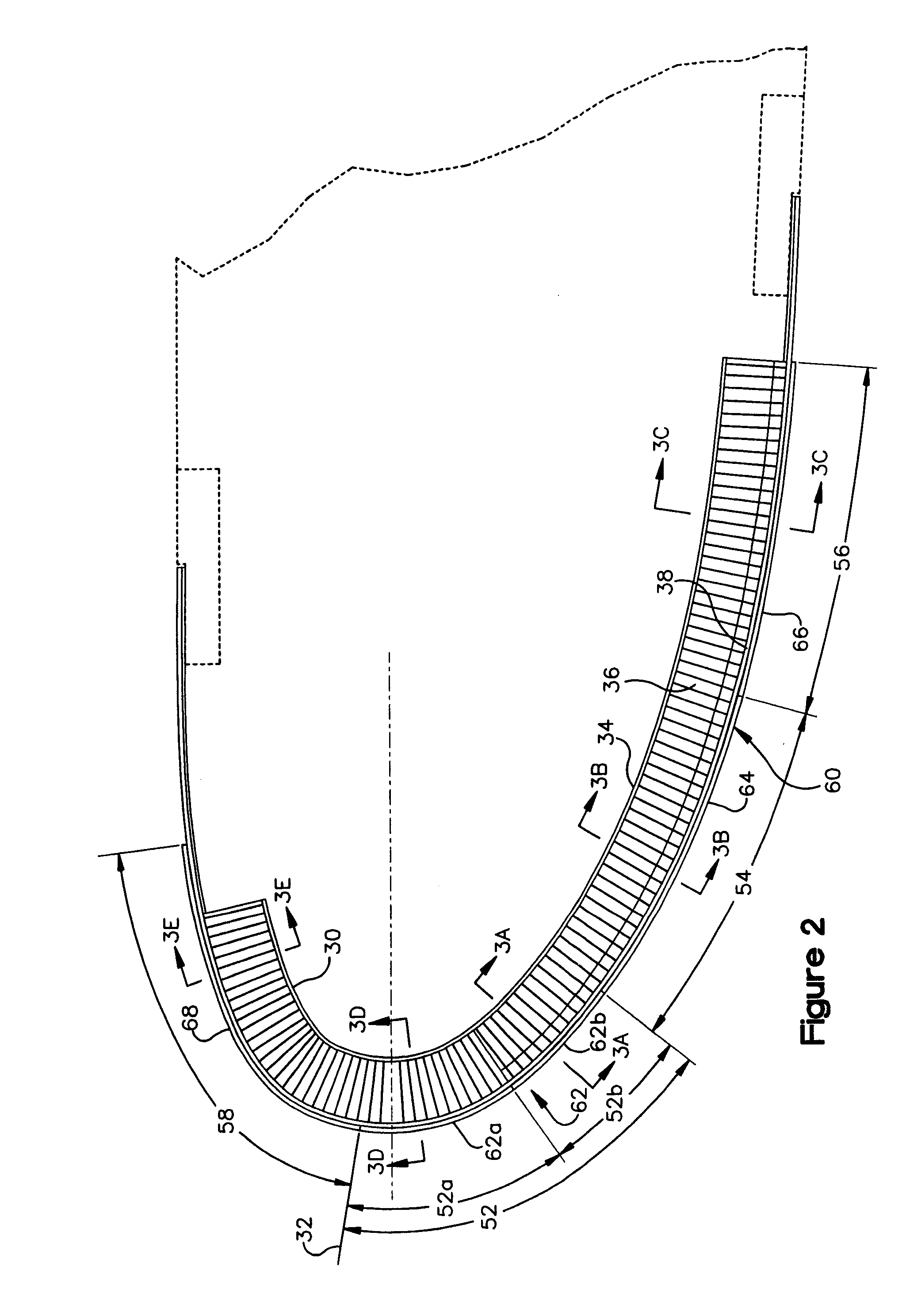
[0014] Referring now to FIG. 2, a cross-section of the nacelle inlet lip 22 is shown. The inlet lip 22 comprises a structural body 30 that defines the leading edge 32 of the nacelle 20...


PUM


Abstract

A nacelle inlet lip (22) for an aircraft engine (16) comprises a structural body (30) and an ice protection system (60). The ice protection system (60) comprises a plurality of ice-protectors (62, 64, 66) independently controllable to allow inner zones (52, 54, 56) to be operated in different modes, different power levels, different time intervals and / or different energy amounts. In this manner, an inner aft zone (52), an inner mid zone (54), and an inner aft zone (56) can be anti-iced and / or de-iced to best preserve desired airflow patterns, to minimize ice particle shed size, and to optimize power consumption.

Description

RELATED APPLICATION [0001] This application claims priority under 35 U.S.C. §119(e) to U.S. Provisional Patent Application No. 60 / 699,214 filed on Jul. 14, 2005. The entire disclosure of this provisional application is hereby incorporated by reference.FIELD OF THE INVENTION [0002] This invention relates generally to an aircraft nacelle ice protection system and, more particularly, to an ice protection system which prevents ice build-up on the inlet lip of an engine nacelle. BACKGROUND OF THE INVENTION [0003] An aircraft typically comprises a fuselage, wings, and engines. Each engine comprises internal engine components (e.g., turbofan components) and a nacelle which houses the internal engine components. Each nacelle includes an inlet lip which defines the inlet opening through which air enters the engine. The formation of ice on the nacelle inlet lip can be a common occurrence during the flight of an aircraft. Ice build-up on the lip can change the contour of the engine's air inlet...

Claims


Application Information

Patent Timeline
Patent Type & Authority Applications(United States)
IPC IPC(8): B64D15/12
CPCB64D15/14B64D33/02B64D2033/0233F02C7/045F02C7/047F05D2250/283
Inventor BOTURA, GALDEMIR C.FLOSDORF, DAVID C.
Owner THE BF GOODRICH CO
Why Eureka
Try Eureka