Servo Mounting System for Direct Drive of an Aircraft Control Surface

Inactive Publication Date: 2007-05-10
DURANT JOHN
View PDF33 Cites 15 Cited by
  • Summary
  • Abstract
  • Description
  • Claims
  • Application Information

AI Technical Summary

Benefits of technology

[0032] (b) Control surface mounting, as shown in FIG. 6A. The mount 1A is installed within the control surface, shown as an elevator aerodynamic member 24, so the axial center of the servo output shaft 15 is located on, and is axially aligned with, the control surface hinge line 12. The servo output shaft 15 is connected directly to the airframe, shown as a horizontal stabilizer aerodynamic member 23,

Problems solved by technology

(3) It decreases routine maintenance in

Method used


Image

  • Servo Mounting System for Direct Drive of an Aircraft Control Surface
  • Servo Mounting System for Direct Drive of an Aircraft Control Surface
  • Servo Mounting System for Direct Drive of an Aircraft Control Surface

Examples


Embodiment Construction

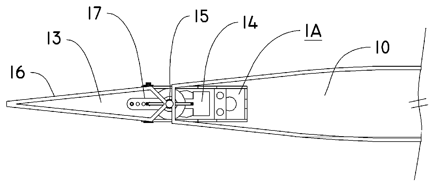
[0068] Although the direct servo drive mount is not limited to a particular aircraft size, material of construction, servo size or servo type—for ease of illustration the following description of embodiment will reference installations in a large model aircraft of 130 inches wingspan. The aircraft is a typical large scale model design, constructed of wood and composite materials. The horizontal stabilizer 23 employs a tubular metal spar 22 onto which the horizontal stabilizer 23 is mounted, permitting removal of the stabilizer as an assembly by sliding it off of the spar 22. The servo being mounted is a generic, commercially available electro-mechanical design, loosely termed in the model industry as “standard” size, with dimensions of 0.76″ by 2.25″ by 1.5″.

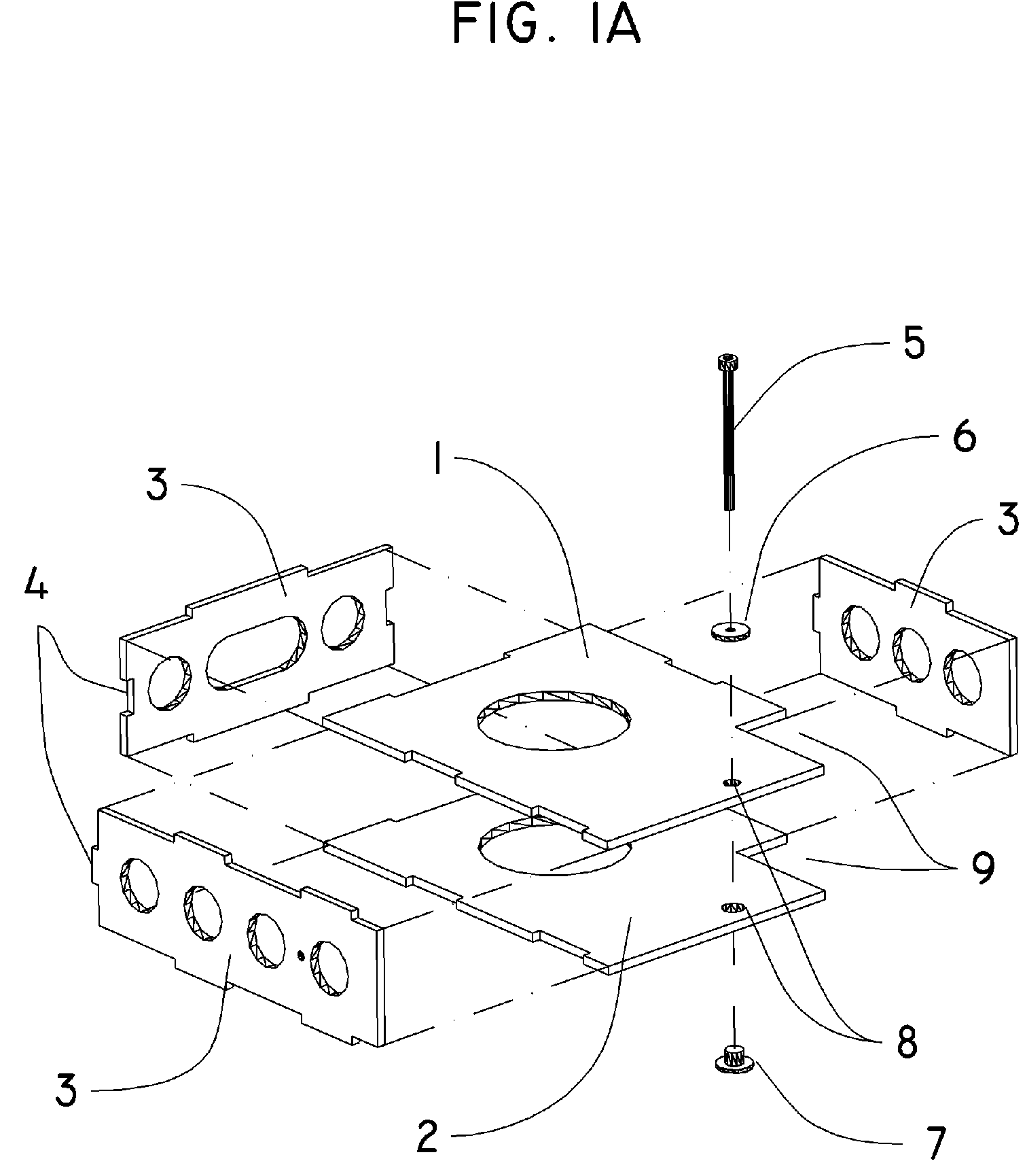
[0069] The direct drive servo mount in FIG. 1A is in the form of a hollow box which is sized to the dimensions of the particular servo being used. Shown are the upper plate 1, lower plate 2, and three sides 3. One side of the m...


PUM


Abstract

This invention is a servo mounting system, which allows a servo with a rotating output shaft to directly power an aircraft control surface. A specially designed servo mount securely positions the servo with the central axis of its rotational output shaft on, and axially aligned with, the hinge line of the control surface it drives. The servo shaft and servo body are directly connected to the airframe and control surface, thereby conserving rotational motion while driving control movement. Electronic means are then used to control the neutral point and the limit of travel of the servo. The system eliminates lost motion without generating adverse linear loads within the drive assembly.

Description

SEQUENCE LISTING [0001] Not Applicable. CROSS-REFERENCE TO RELATED APPLICATIONS [0002] Not Applicable. STATEMENT REGARDING FEDERALLY SPONSORED RESEARCH OR DEVELOPMENT [0003] Not Applicable. THE NAMES OF THE PARTIES TO A JOINT RESEARCH AGREEMENT [0004] Not Applicable. INCORPORATION-BY-REFERENCE OF MATERIAL SUBMITTED ON A COMPACT DISC [0005] Not Applicable. BACKGROUND OF THE INVENTION [0006] 1. Field of the Invention [0007] This servo mount design is related to the specific connection between the device or arrangement for controlling an aircraft and a controlled element. [0008] 2. Description of Related Art including information disclosed under 37 CFR 1.97 and 1.98. [0009] It is often necessary or desirable to power the motion of an aircraft control surface with an electro-mechanical servo. The most common use of servo powered flight controls is in the radio controlled aircraft hobby industry. There is also a rapidly growing market for commercial and military remotely piloted vehicles...

Claims


Application Information

Patent Timeline
IPC IPC(8): B64C9/02
CPCA63H27/02B64C9/02B64C13/50Y02T50/32Y02T50/44Y02T50/545Y02T50/54Y02T50/30Y02T50/40Y02T50/50
Inventor DURANT, CECIL JOHN
Owner DURANT JOHN
Why Eureka
Try Eureka