Display unit, method of manufacturing same, organic light emitting unit, and method of manufacturing same

a display unit and organic light technology, applied in the field of display units, can solve the problems of limiting the patterning precision, the alignment accuracy of the metal mask, and the design and formation of the function layer of the light emitting device of each color, so as to achieve the effect of jumboizing the display size and ensuring the utilization efficiency of ligh

Inactive Publication Date: 2007-05-10
SONY CORP
View PDF8 Cites 398 Cited by
  • Summary
  • Abstract
  • Description
  • Claims
  • Application Information

AI Technical Summary

Benefits of technology

[0025] In the display unit with such a configuration, since the display unit includes the foregoing organic light emitting unit. Therefore, it is not necessary to separately coat the light emitting layer by using a metal mask in manufacturing the display unit, and it is not necessary to convert light generated in the light emitting layer to other colors by color filters. Thereby, the display size can be jumboized, and utilization efficiency of light can be secured.

Problems solved by technology

Therefore, designing and forming the function layer in the light emitting device of each color have been very complicated.
However, when vapor deposition or coating using a metal mask is performed, there is a limit of alignment accuracy of the metal mask.
When inkjet is used, there is a limit of the patterning precision.
Therefore, it is hard to miniaturize and jumboize the light emitting device and space between the light emitting devices.
Further, the foregoing limits are the cause of preventing realization of the display unit capable of higher definition display.
However, in the configuration of (2), the color filter absorbs unnecessary light emitting component, and therefore light emission efficiency is lowered, leading to large load on the electric power consumption and device life.
Further, it is difficult to provide filtering white light emission in the light emitting device into blue, green, and red with favorable color purity by transmission characteristics of the color filters capable of being mass-produced, and only the display unit in which the extracted light has a wide wavelength distribution and poor color reproducibility can be produced.
Further, in the configuration of (3), there are problems of low conversion efficiency of the color conversion filters, difficulty of manufacturing the color conversion filters, life of the color conversion filters, color purity of emitted light colors after color conversion and the like, and therefore it is hard to put the configuration in practical use.

Method used


Image

  • Display unit, method of manufacturing same, organic light emitting unit, and method of manufacturing same
  • Display unit, method of manufacturing same, organic light emitting unit, and method of manufacturing same
  • Display unit, method of manufacturing same, organic light emitting unit, and method of manufacturing same

Examples


example 1

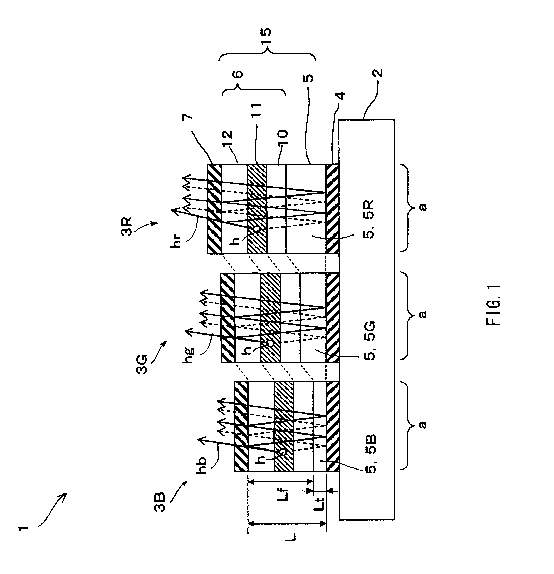
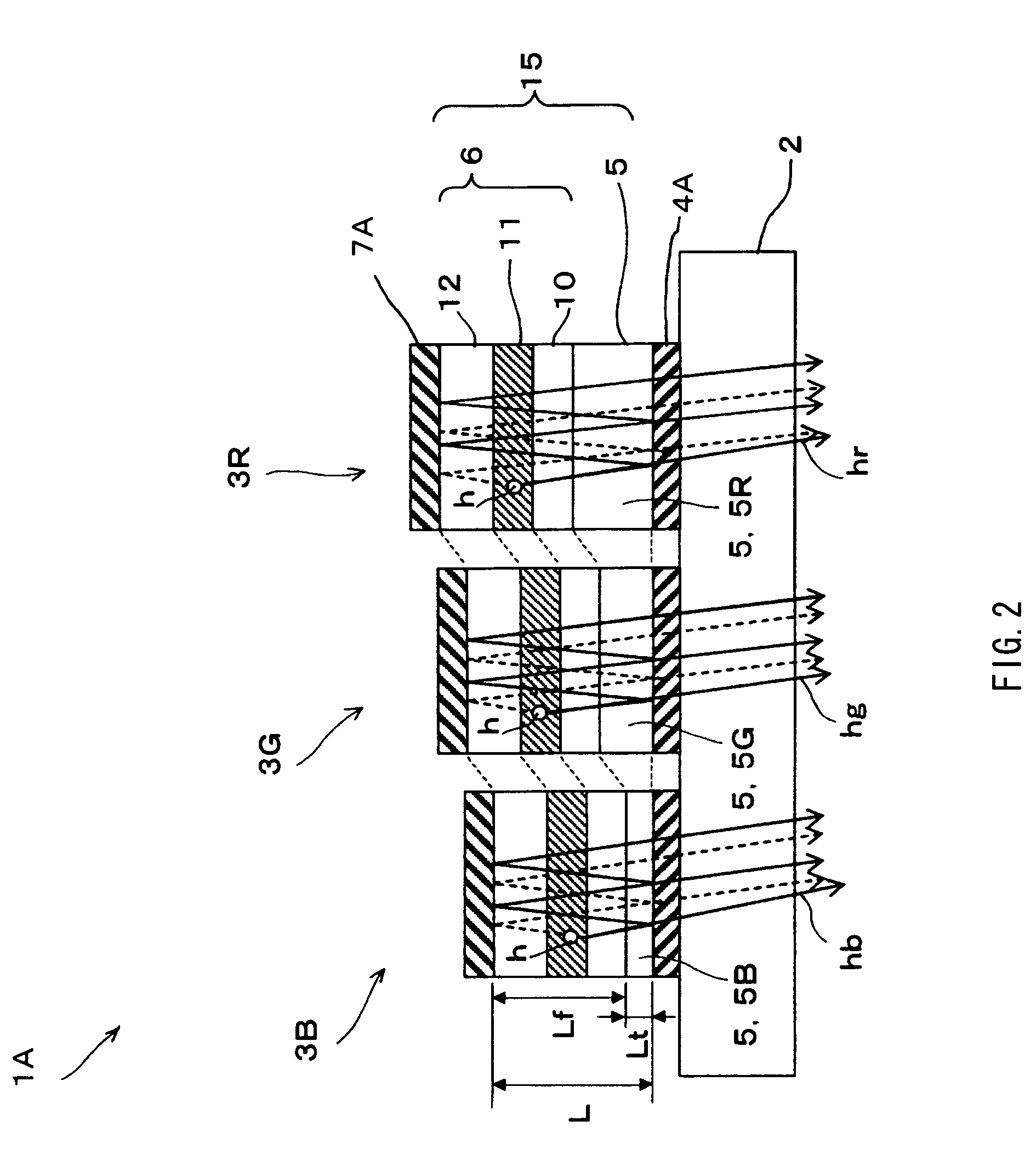
[0191] In Example 1, the top emission type display unit 1 for performing full color display, which has been described with reference to FIG. 1, was fabricated as follows.

[0192] First, on the substrate 2 made of a glass plate, the lower electrode 4 made of chromium (film thickness as about 100 nm) as an anode becoming a mirror, and the transparent conductive layers 5B, 5G, and 5R made of ITO with each film thickness were pattern-formed. Next, a cell for organic EL device, in which regions other than light emitting regions of 2 mm×2 mm in the surface central portions of the transparent conductive layers 5B, 5G, and 5R were masked by an insulating film (not shown) was fabricated. Next, a metal mask having an aperture over the exposed portions of the transparent conductive layers 5B, 5G, and 5R becoming each light emitting region was arranged over the substrate 2 in proximity thereto, and the function layer 6 of the organic EL device having the light emitting spectrum through blue, gre...

example 2

[0194] The display unit 1 was fabricated as in Example 1, except that the optical distances Lt and Lf were set so that the value of m became m (blue)=1, m (green)=0, and m (red)=0, that is, the film thickness of the function layer 6 was 80 nm, the film thickness of the cathode was 9 nm, and the optical distance Lt was Lt (blue)=110 nm, Lt (green)=10 nm, and Lt (red)=44 nm. The reflectance of the cathode in this case was 30% with respect to light with wavelength of 550 nm.

example 3

[0195] The display unit 1 was fabricated as in Example 1, except that the optical distances Lt and Lf were set so that the value of m became m (blue)=1, m (green)=1, and m (red)=0, that is, the film thickness of the function layer 6 was 105 nm, the film thickness of the cathode was 6 nm, and the optical distance Lt was Lt (blue)=85 nm, Lt (green)=135 nm, and Lt (red)=10 nm. The reflectance of the cathode in this case was 15% with respect to light with wavelength of 550 nm.


PUM


Abstract

A display unit capable of being simply designed and manufactured by using more simplified light emitting device structure while capable of high definition display and display with superior color reproducibility and a manufacturing method thereof are provided. The display unit is a display unit (1), wherein a plurality of organic EL devices (3B), (3G), and (3R), in which a function layer (6) including a light emitting layer (11) is sandwiched between a lower electrode (4) made of a light reflective material and a semi-transmissive upper electrode (7), and which has a resonator structure in which light h emitted in the light emitting layer (11) is resonated using a space between the lower electrode (4) and the upper electrode (7) as a resonant section (15) and is extracted from the upper electrode (7) side are arranged on a substrate (2). In the respective organic EL devices (3B), (3G), and (3R), the function layer (6) is made of an identical layer, and an optical distance L of the resonant section (15) is set to a value different from each other so that blue, green, or red wavelength region is resonated.

Description

TECHNICAL FIELD [0001] The present invention relates to a display unit, a manufacturing method thereof, an organic light emitting unit, and a manufacturing method thereof. The present invention particularly relates to a surface light emitting type display unit, in which light emitting devices such as an organic EL device are arranged and formed on the substrate and a desired light emitting color can be selectively extracted, a manufacturing method thereof, an organic light emitting unit, and a manufacturing method thereof. BACKGROUND ART [0002] In recent years, as a display unit taking the place of the cathode ray tube (CRT), research and development of light weighted and small flat display units with small electric power consumption has been actively implemented. Of the foregoing, a display unit using an organic light emitting unit including a self-light emitting display device (so-called light emitting device) such as an inorganic EL device and an organic EL device attracts attent...

Claims


Application Information

Patent Timeline
Patent Type & Authority Applications(United States)
IPC IPC(8): H01L31/113H01L27/32H01L51/52H05B33/10H05B33/12H05B33/14H05B33/24
CPCH01L27/3211H01L51/5203H01L27/153H01L2251/5315H01L2251/558H01L51/5265H10K59/30H10K59/35H10K50/818H10K50/828H10K50/852H10K2102/3026H10K2102/351H10K59/805H10K50/805H10K59/38H10K50/81H10K50/82H10K50/813H10K50/824H10K50/841H10K50/856H10K59/124H10K59/131H10K59/1315
Inventor KASHIWABARA, MITSUHIROYAMADA, JIROYOKOYAMA, SEIICHIHANAWA, KOHJI
Owner SONY CORP
Why Eureka
Try Eureka