Motor vehicle with at least two movable parts

a technology of motor vehicles and movable parts, applied in the direction of roofs, mechanical equipment, transportation and packaging, etc., can solve the problem that the roof concept does not allow the conversion of roofs, and achieve the effect of simplifying the movement of laterally adjacent roof parts and more stability

Inactive Publication Date: 2007-05-10
MAGNA CAR TOP SYST GMBH
View PDF3 Cites 3 Cited by
  • Summary
  • Abstract
  • Description
  • Claims
  • Application Information

AI Technical Summary

Benefits of technology

[0012] According to another aspect of the invention, the two laterally adjacent movable parts of the roof can be moved by a motor drive. The two laterally adjacent movable parts can be relatively small because they are disposed next to one another. Even though relatively small roof parts are provided, a large roof opening can be provided because each part extends between the side frame immediately adjacent to the roof part and the middle of the roof. Both laterally adjacent roof parts border one another in the middle of the roof. The laterally adjacent roof parts have less surface area than roof parts which extend over the entire width of the roof because they extend across only half of the width of the roof. The weight of each roof part may be minimized and less force is required to drive each roof part to a desired position.
[0015] A longitudinal member may be securely fastened to the body in the middle of the roof opening. The inside edges of the laterally adjacent roof parts may be guided or supported by the longitudinal member. The longitudinal member may provide substantially more stability and may also simplify the movement of the laterally adjacent roof parts from the closed position into the open position. For example, each roof part can be guided with respect to the roof sections fastened to the body on three bearing units. Two of the bearing units may lie on the outside front and outside back areas, respectively, and one bearing unit may lie on the inside front side area of each roof part. The later bearing unit may be supported by the central longitudinal member that is fastened to the body. To open the roof, the movable parts may be moved in the direction of the vehicle's longitudinal axis. If the parts are moved in the direction of the longitudinal axis, each roof part's inner front bearing unit that is supported and guided on the longitudinal member can travel along the longitudinal member toward the back of the vehicle. When one of the laterally adjacent roof parts is open, the outer back bearing unit may be disposed in the back area of the roof frame and the inner front bearing unit may be located at the back of the central longitudinal member.
[0018] According to another aspect of the invention, one or more roof parts may be made of a transparent material such as, for example, polycarbonate or glass. By using a transparent material for the roof part the vehicle interior may be provided with light through the roof part into the vehicle interior even when the motor vehicle roof is in its closed position.

Problems solved by technology

This roof concept does not allow for converting the roof to a convertible position.

Method used


Image

  • Motor vehicle with at least two movable parts
  • Motor vehicle with at least two movable parts
  • Motor vehicle with at least two movable parts

Examples


Embodiment Construction

)

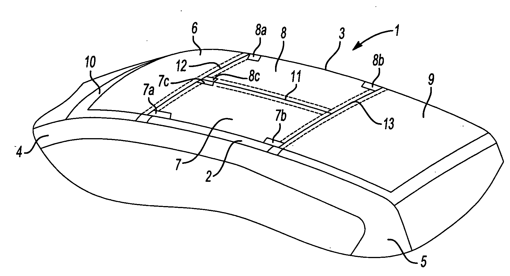
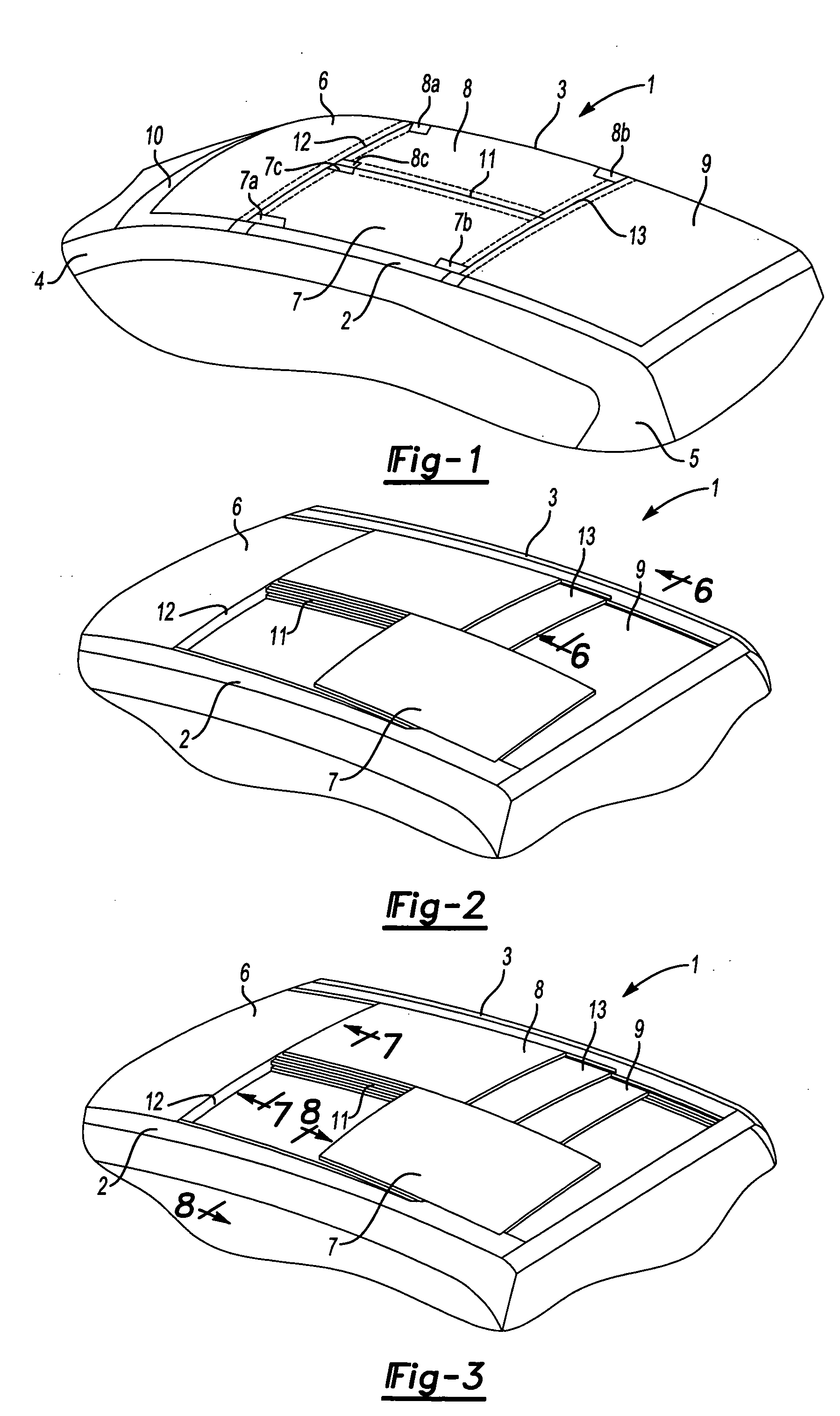
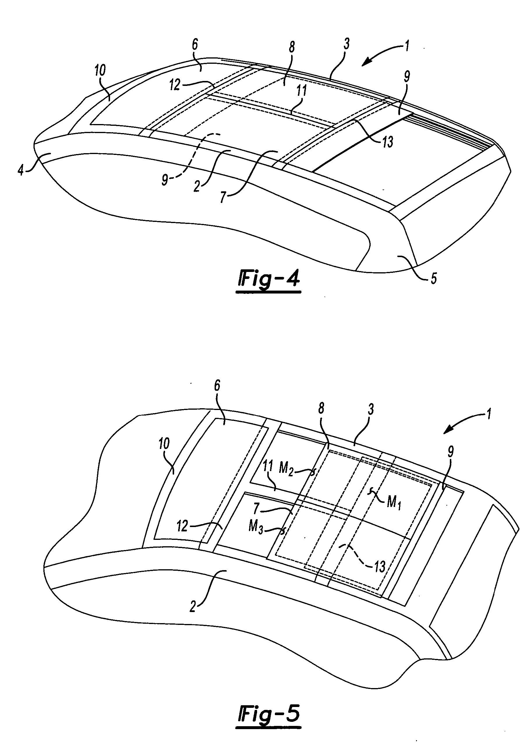
[0030] Referring to FIG. 1, a motor vehicle roof 1 is illustrated that has side roof frames 2, 3 that are permanently connected to the body of the motor vehicle. The side roof frames 2 merge into the body's A-pillars 4 in the front area of the motor vehicle. The side roof frames merge into the body's C-pillars 5 in the back area of the motor vehicle. Roof parts 6, 7, 8 and 9 lie in a roof opening that may be selectively covered by the roof parts 6-9. Front roof part 6 is located adjacent to a cross member 10, or header, of the windshield frame of the vehicle. Front roof part 6 extends between the two roof frames 2 and 3 and spans the entire width of the roof. Two parallel, or laterally adjacent, roof parts 7 and 8 are provided behind front roof part 6. Roof parts 7 and 8 may also be referred to as side front roof parts. Roof parts 7 and 8 are disposed parallel to the motor vehicle's longitudinal axis and extend across half of the width of the roof. Back roof part 9 is disposed in t...


PUM


Abstract

A motor vehicle roof having at least two laterally adjacent parts with respect to the motor vehicle's longitudinal axis when the parts are in a closed position. The laterally adjacent parts may be moved between the closed position and an open position by moving one or both of the laterally adjacent parts in a translational movement parallel to the longitudinal axis of the vehicle. The laterally adjacent parts are retained between and parallel to two side roof frames that are permanently connected to the body. The laterally adjacent parts may be moved to an open position above or below a rear roof panel. The rear roof panel extends across the vehicle in a transverse direction between the side roof frames and is movable in a longitudinal direction to a position above or below the laterally adjacent roof panels. A front roof panel may be provided that may be raised on a back edge to provide a wind deflector.

Description

CROSS-REFERENCE TO RELATED APPLICATIONS [0001] This application is a continuation-in-part of U.S. application Ser. No. 11 / 062,379 filed Feb. 22, 2005, which, in turn, claims priority to German application 10 2004 009 049.1 filed Feb. 23, 2004.BACKGROUND OF THE INVENTION [0002] 1. Field of the Invention [0003] The present invention relates to a motor vehicle roof that has several movable panels that may be moved independently between a closed position and a variety of open positions. [0004] 2. Background Art [0005] Motor vehicle roofs are available that include retractable hard tops, convertible tops, hard tops having sun roofs, and hard tops having removable targa tops. [0006] One example of a hard top motor vehicle roof is disclosed in published German application DE 101 13 427 A1 that has two rigid parts that are disposed next to one another with respect to the longitudinal axis of the vehicle when the roof is closed. The panels are stored in a storage compartment at the back of t...

Claims


Application Information

Patent Timeline
Patent Type & Authority Applications(United States)
IPC IPC(8): B60J7/043B60J7/04
CPCB60J7/047
Inventor HESSE, JANHALBWEISS, THOMAS
Owner MAGNA CAR TOP SYST GMBH
Why Eureka
Try Eureka