Image stabilized digital imaging

Active Publication Date: 2007-05-10
NOKIA TECHNOLOGLES OY
View PDF8 Cites 40 Cited by
  • Summary
  • Abstract
  • Description
  • Claims
  • Application Information

AI Technical Summary

Benefits of technology

[0015] Furthermore, the invention concerns also method in digital imaging procedure in which method in connection with the imaging procedure is detected a movement effect caused by an external source aimed to the device and at least part of optics arranged to form an image on an image sensor is actuated based on the said detected movement effect. In the method the actuation of the said optics is based on deformations.
[0016] Furthermore, the optical image stabilizer unit to which the invention also relates, is intended to an electronic device including a camera unit which camera unit includes an image sensor and an optics for forming an image on the image sensor, and which said optical image stabilizer unit may be arrange to actuate at least part of the said optics in order to compensate the detected movement effect caused by the external source. In the unit the actuation of the said optics is based on deformations arranged to be taken place in the optical image stabilizer unit.
[0017] Furthermore, the program product for actuating an optical image stabilizer unit in a electronic device including a camera unit, includes a storing means and a program code executable by a processor and written in the storing means, and which program code includes first code means configured to detect a movement effect caused by an external source aimed to the device in connection with an imaging procedure and second code means configured to actuate at least part of the said optics arranged to form an image on an image sensor by the said optical image stabilizer unit which actuation is configured to base on the said detected movement effect. The program code includes also third code means configured to cause deformations in connection with the said optical image stabilizer unit in order to actuate the said optics.
[0018] Owing to the invention, numerous advantages to carry out image

Problems solved by technology

In certain situations when users of digital imaging apparatuses perform an imaging procedure, for example, with high resolution/zoom factor, low sensitivity sensor, long exposure time (night-shot) and with a lightweight device (e.g. mobile phone), hand shaking can very easily result blurred, out-of-focus images.

Method used


Image

  • Image stabilized digital imaging
  • Image stabilized digital imaging
  • Image stabilized digital imaging

Examples


Example

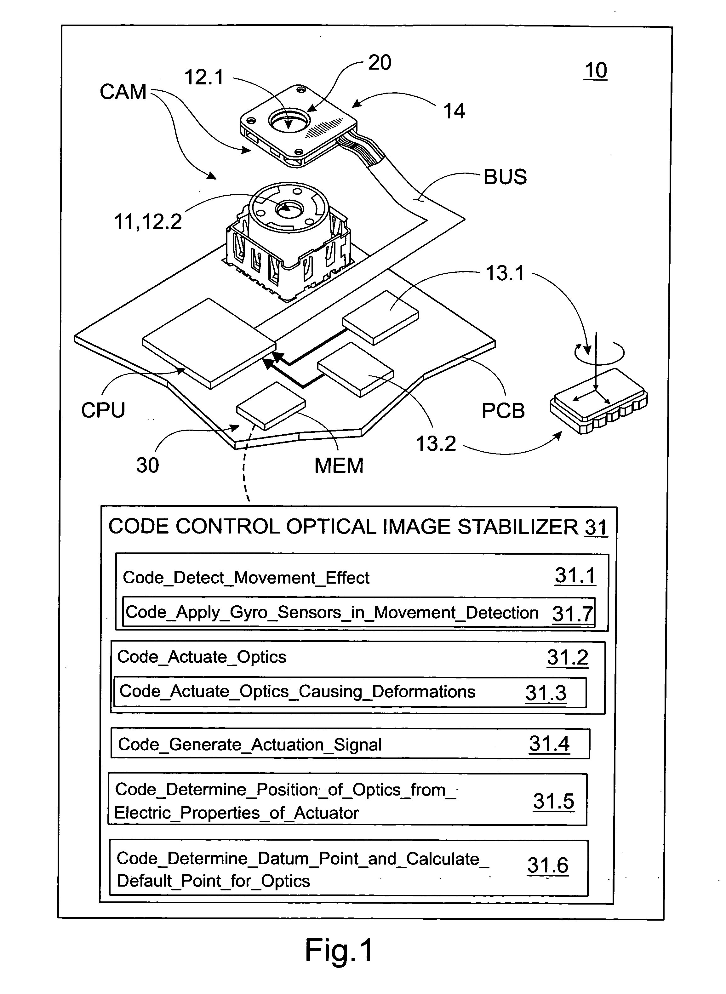
[0030]FIG. 1 shows an example of electronic device 10 according to the invention. In general, the device 10 according to the invention may be a portable digital camera device 10. More particular, the device 10 according to the invention may be, for example, mobile device, such as, for example, mobile phone, PDA device (Personal Digital Assistant) or some equivalent intelligent communication device (“smart device”) equipped with camera unit CAM. Of course, the device 10 may also be digital camera without any special communication features. The properties of the camera unit CAM and imaging chain connected to that may permit several kind of imaging modes, such as, for example, still and / or video imaging.

[0031] Next the device 10 will be described in a manner that is more focused to the invention. For the skilled person, it is well known that the device 10 may also include other such functionalities, which are not required to describe in this application context more detailed manner. I...


PUM


Abstract

An electronic device is disclosed, which includes an image sensor, an optics for forming an image on the image sensor, a detector for detecting a movement effect caused by an external source aimed to the device in connection with an imaging procedure and an optical image stabilizer unit arranged to actuate at least part of the said optics in order to compensate the detected movement effect caused by the external source. The actuation of the said optics is based on deformations arranged to take place in the optical image stabilizer unit. In addition the invention also relates to corresponding method, optical image stabilizer unit and program product for actuating the said unit.

Description

FIELD OF THE INVENTION [0001] The invention relates to an electronic device, which includes [0002] an image sensor, [0003] an optics for forming an image on the image sensor, [0004] a detector for detecting a movement effect caused by an external source aimed to the device in connection with an imaging procedure and [0005] an optical image stabilizer unit arranged to actuate at least part of the optics in order to compensate the detected movement effect caused by the external source. [0006] In addition, the invention also concerns method, optical image stabilizer unit and corresponding program product for actuating the said unit. BACKGROUND OF THE INVENTION [0007] In certain situations when users of digital imaging apparatuses perform an imaging procedure, for example, with high resolution / zoom factor, low sensitivity sensor, long exposure time (night-shot) and with a lightweight device (e.g. mobile phone), hand shaking can very easily result blurred, out-of-focus images. This effec...

Claims


Application Information

Patent Timeline
IPC IPC(8): H04N5/228H04N23/55H04N23/57H04N23/68H04N23/75
CPCG02B27/646H04N5/2254H04N5/2257H04N5/23248H04N5/23258H04N5/23287G03B2205/0061G03B5/00G03B2205/0015G03B2217/005G03B2205/0076H04N23/57H04N23/55H04N23/68H04N23/6812H04N23/687G02B27/64H04N23/00H04N23/75
Inventor EROMAKI, MARKO
Owner NOKIA TECHNOLOGLES OY
Why Eureka
Try Eureka