Device for dispersing light pulses of which the spectral amplitude is programmable

Inactive Publication Date: 2007-05-10
FASTLITE
View PDF4 Cites 23 Cited by
  • Summary
  • Abstract
  • Description
  • Claims
  • Application Information

AI Technical Summary

Benefits of technology

[0008] The invention is therefore intended more specifically to overcome this disadvantage. It proposes a device for dispersing light pulses of an optical beam constituted by two dispersive prisms, with the same vertex angle, mounted head to tail, the optical input surface of the first prism being parallel to the optical output surface of the second prism, the distance separating said optical input surface of the first prism and said optical output surface of the second prism being a

Problems solved by technology

It appears that all of these devices for dispersing brief light pulses do not make it possible

Method used


Image

  • Device for dispersing light pulses of which the spectral amplitude is programmable
  • Device for dispersing light pulses of which the spectral amplitude is programmable
  • Device for dispersing light pulses of which the spectral amplitude is programmable

Examples


Embodiment Construction

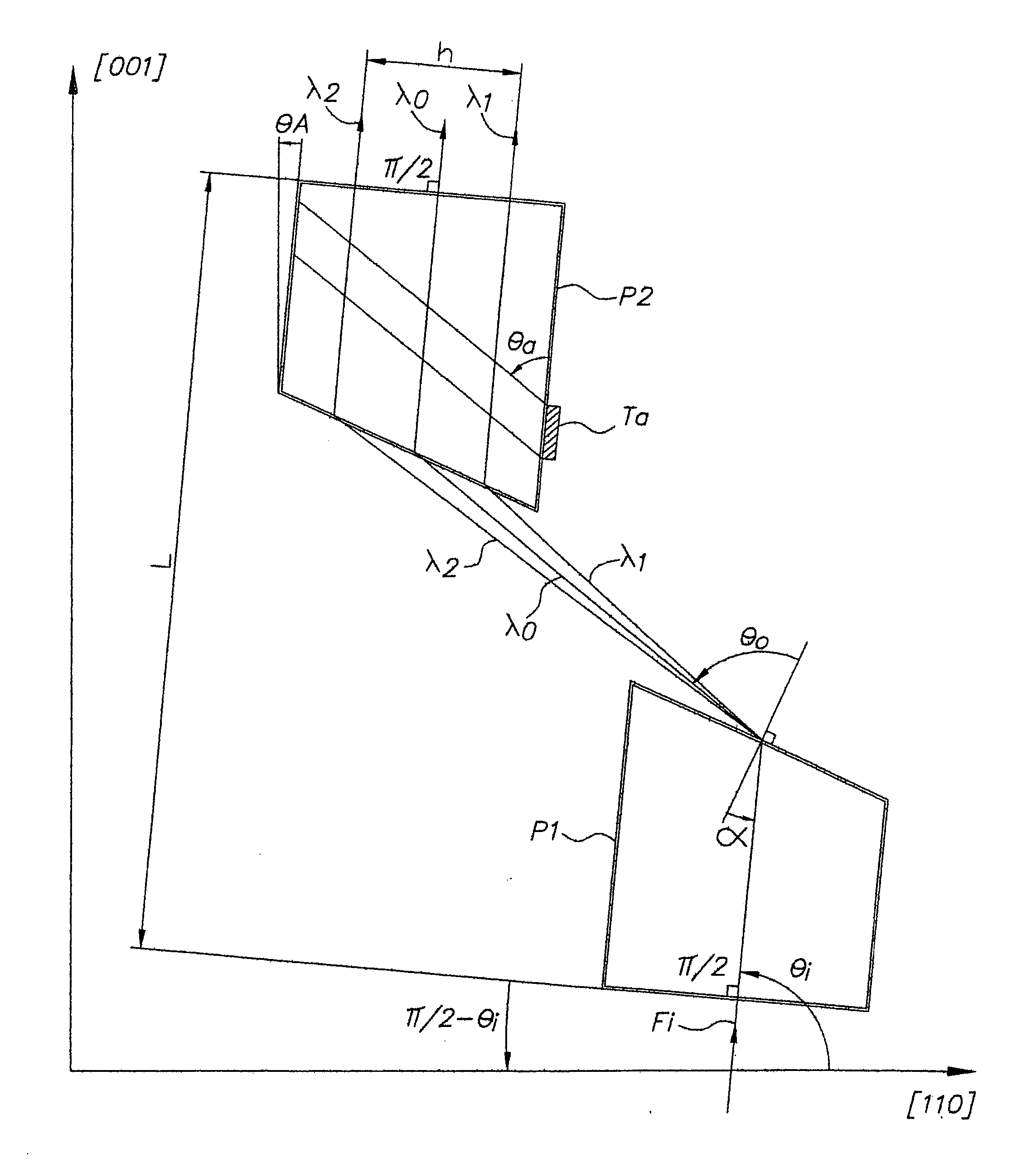
[0022] In the example shown in FIG. 1, two prisms P1, P2, with the same vertex angle a, are arranged head to tail, the input surface of said prism P1 is parallel to the output surface of said prism P2, the distance separating them being L; the output surface of said first prism P1 is consequently parallel to the input surface of said prism P2, the distance separating them being d; the projection of the vertex of said prism P2 on the input surface of said prism P1 is separated by H from the vertex of said prism P1.

[0023] An optical incident beam Fi is diffracted by the prism P1, which resulting diffraction is represented by three optical paths having a wavelength λ1, λ2, on each side of a central wavelength λ0, which paths are again diffracted in the second prism P2; at the output of the second prism P2, the three optical paths having a wavelength λ0, λ1 , λ2, are spatially separated from one another and parallel to the incident beam Fi, the dispersion associating the delay time wit...


PUM


Abstract

Device for dispersion of light pulses of an optical beam (Fi) constituted by two dispersive prisms (P1, P2), with the same vertex angle (α), mounted head to tail, the optical input surface of the first prism (P1) being parallel to the optical output surface of the second prism (P2), the distance (L) separating said optical input surface of the first prism (P1) and said optical output surface of the second prism (P2) being adjustable, given that the material constituting at least one of said first and second prisms (P1, P2) is an acousto-optic material allowing for acousto-optic interaction between said optical beam and an acoustic beam, the acoustic wave of said acoustic beam generating, in at least one of said first and second prisms (P1, P2), an integrated deflective Bragg cell.

Description

BACKGROUND OF THE INVENTION [0001] 1. Field of the Invention [0002] This invention relates to a device for dispersion of light pulses programmable in spectral amplitude. [0003] 2. Description of the Prior Art [0004] In general, it is known that there are numerous devices for dispersing brief light pulses. One of them, proposed for the first time by R. L. Fork et al, “Negative dispersion using pairs of prisms”, published in Optics Letters, May 1984, consists of using a train of two identical reversed prisms (the input surface of the first prism is parallel to the output surface of the second prism). [0005] In the example shown in FIG. 1, describing the prior art relating in particular to the device cited above, two prisms P1, P2, having the same vertex angle a, are arranged head to tail, the input surface of said prism P1 is parallel to the output surface of said prism P2, the distance separating them being L; the output surface of said first prism P1 is consequently parallel to the ...

Claims


Application Information

Patent Timeline
IPC IPC(8): G02B27/28
CPCG01J3/1256G02F1/11G02F1/33
Inventor KAPLAN, DANIELTOURNOIS, PIERRE
Owner FASTLITE
Why Eureka
Try Eureka