Atmospheric turbulence hazard detector

a hazard detector and atmospheric turbulence technology, applied in the direction of instruments, transmission monitoring, clear air turbulence detection/forecasting, etc., can solve the problems of short detection range, dangerous loss of altitude, and severe aircraft hazards

Inactive Publication Date: 2007-05-10
RUBIN WILLIAM L
View PDF7 Cites 23 Cited by
  • Summary
  • Abstract
  • Description
  • Claims
  • Application Information

AI Technical Summary

Problems solved by technology

Hazardous Turbulence Detection: Clear air turbulence, microbursts, aircraft wake vortices, gust fronts, thunderstorms, updrafts, downdrafts, and convective flows all present severe hazards to aircraft.
Consequently, acoustic reflections are weak for UHF and microwave radar, resulting in short detection ranges.
Vortices produced by large and heavy aircraft are hazardous to smaller aircraft since they can induce rolling moments that exceed the smaller aircraft's roll control authority, causing a dangerous loss of altitude, and possible structural failure.
Vortex encounters are especially hazardous in the terminal area where light aircraft follow heavy aircraft on the same glide slope and where recovery from an upset may not be possible because of low aircraft altitude.
Because a strong crosswind moves wake vortices out of the glide path fairly quickly, FAA spacings are overly conservative most of the time.
GWVSS, however, is not operationally deployed because poles are not permitted near airport glide slopes for safety reasons.
RASS, however, emits a loud annoying sound, is costly, and expensive to maintain.
When the downdraft reaches the ground, it generates an outburst of damaging wind flow.
Nicrobursts typically last less than 10 minutes and are hazardous to aircraft during takeoff and landing.
This system, however, determines the existence of a microburst in the vicinity of the aircraft and does not provide a timely waning for the avoidance of the microburst.
LLWAS, however, has poor spatial resolution along the arrival glide slope and departure corri

Method used


Image

  • Atmospheric turbulence hazard detector
  • Atmospheric turbulence hazard detector
  • Atmospheric turbulence hazard detector

Examples


Embodiment Construction

[0045] A flow is laminar or turbulent depending on the value of its Reynolds number Re, which is given by Re=UL / v, where L is a characteristic length of the flow, U is a characteristic speed of the flow, and v is the fluid kinematic coefficient of viscosity. When the Reynolds number is below a critical value, viscosity smooths out lateral velocity variations, and laminar flow is favored.

[0046] As the Reynolds number increases above a critical value, the flow becomes unstable so that a small disturbance produces irregular eddying motion. The largest scale eddies appear first. These eddies are also unstable due to having high Reynolds numbers and break down into smaller second order eddies. Second order eddies generally also have high Reynolds numbers and break down into smaller third order eddies. This process continues until eddies with Reynolds numbers below a critical value are reached. These eddies dissipate, their energy expended overcoming frictional forces. The largest scale ...


PUM


Abstract

An Atmospheric Turbulence Detector utilizes a sensor to detect noise and extracts infrasound having frequencies below a specified infrasound frequency. A threshold is computed from the detection of infrasound in the vicinity of the sensor prior to the arrival of infrasound from the turbulence and an alarm is given when the infrasound from the turbulence exceeds the computed threshold. Range and direction of atmospheric turbulence are determined with the utilization of two sensors, measuring the phase difference between the detected infrasound of the two sensors, measuring amplitude differences of the infrasound detected at two separate locations.

Description

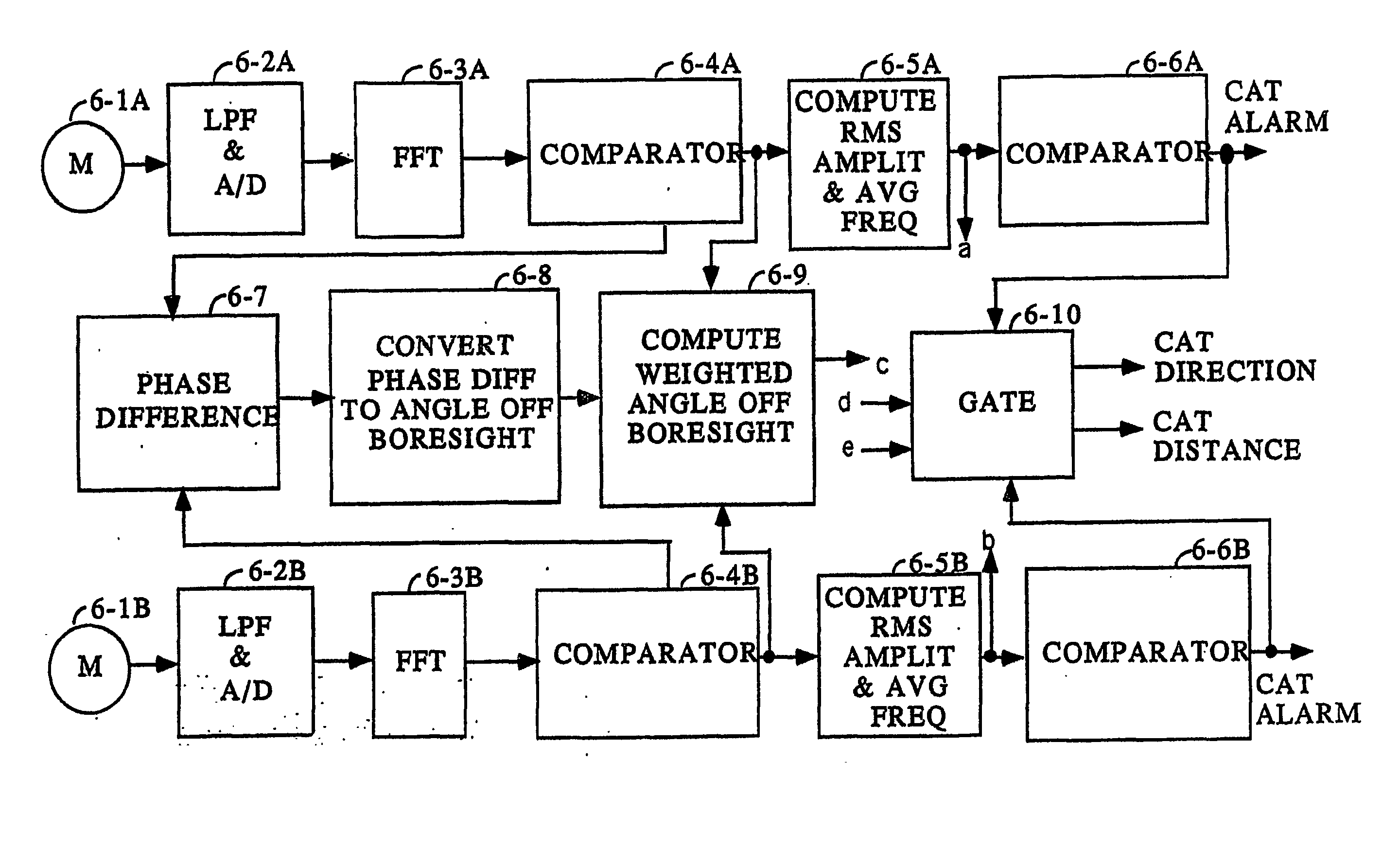
[0001] The priority benefit of Provisional Application No. 60 / 503,927 filed Sep. 17, 2003 is claimed by this application.BACKGROUND OF THE INVENTION [0002] 1. Field of the Invention [0003] The invention relates generally to the detection of hazardous atmospheric turbulence, and more particularly to the detection of aircraft wake vortices, microbursts, and tornadoes near the ground, and Clear Air Turbulence (CAT) at high altitude. [0004] 2. Description of the Prior Art [0005] Hazardous Turbulence Detection: Clear air turbulence, microbursts, aircraft wake vortices, gust fronts, thunderstorms, updrafts, downdrafts, and convective flows all present severe hazards to aircraft. Effects on aircraft encountering any of these hazards range from severe buffeting to the ultimate catastrophe. A system for detecting such hazards is disclosed in U.S. Pat. No. 6,480,142 issued to W. L. Rubin. Hazardous turbulence is detected with the utilization of Doppler shifted frequencies of received radar si...

Claims


Application Information

Patent Timeline
IPC IPC(8): G01W1/10G01B
CPCG01W1/10G01W2001/003
Inventor RUBIN, WILLIAM L.
Owner RUBIN WILLIAM L
Why Eureka
Try Eureka