Substrate for optical fiber array and method for fabricating the same

a technology of substrate and optical fiber, applied in the direction of optics, instruments, optical light guides, etc., can solve the problems of increasing cost, difficulty or complexity in adjusting internal pressure to an appropriate value, and reducing the height difference of the plurality of optical fibers retained in these grooves, so as to facilitate and accurately fabricate the preliminary. , the effect of enhancing the accuracy of positioning of optical fibers

Inactive Publication Date: 2007-05-10
NIPPON ELECTRIC GLASS CO LTD
View PDF5 Cites 2 Cited by
  • Summary
  • Abstract
  • Description
  • Claims
  • Application Information

AI Technical Summary

Benefits of technology

[0032] With such structure, it is possible to easily and accurately fabricate the preliminary preform having, on the top, the plurality of large grooves which correspond to the plurality of ideal grooves of the optical-fiber aligning part obtained by the drawing. The preliminary preform is fabricated only such that each groove has the substantially the same size, shape and pitch with respect to the surface, which is a plane. Thus, a complicated process or the like is not needed and the fabrication of the preliminary preform is favorable for achieving the ideal state of each groove accurately.
[0033] As described above, according to the substrate for the optical-fiber aligning part related to the present invention, the optical-fiber aligning part of said substrate is formed such that the depths of the grooves provided at the center portion are relatively shallower and those of the grooves provided at both ends in widthwise direction are relatively deeper, with the center portion on the top-surface in the widthwise direction being recessed. Therefore, the height difference of the plurality of optical fibers retained in these grooves can be effectively reduced, thereby enhancing the accuracy of the positioning of optical fibers. In addition, when the substrate having the optical-fiber aligning part of which the center portion of the top-surface is re

Problems solved by technology

However, even according to the fabricating method disclosed in Patent Document 2, an apparatus controlling the internal pressure of the through hole is required, and this makes the drawing apparatus larger and more complicated and hence leads to increase in cost.
Moreover, adjusting the internal pressure to an appropriate value would be difficult or complicated.
In addition, even when the recess at the center portion of the surface in the widthwise direction is being corrected by increasing the internal pressure of the through hole in such a manner, it can be assumed that only part of the surface is likely to be corrected and it will be difficult to make the entire surface flat.
Therefore, all the height differences between the V-grooves provided at the ce

Method used


Image

  • Substrate for optical fiber array and method for fabricating the same
  • Substrate for optical fiber array and method for fabricating the same
  • Substrate for optical fiber array and method for fabricating the same

Examples


examples

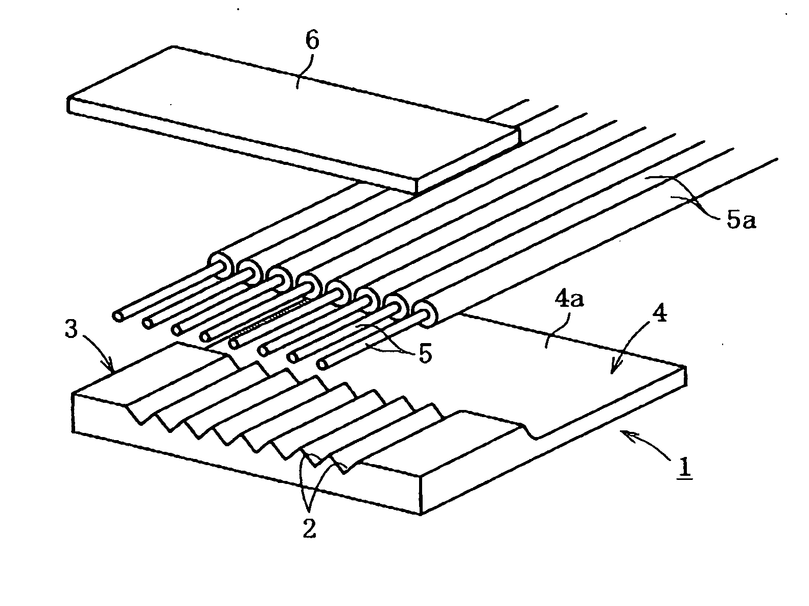
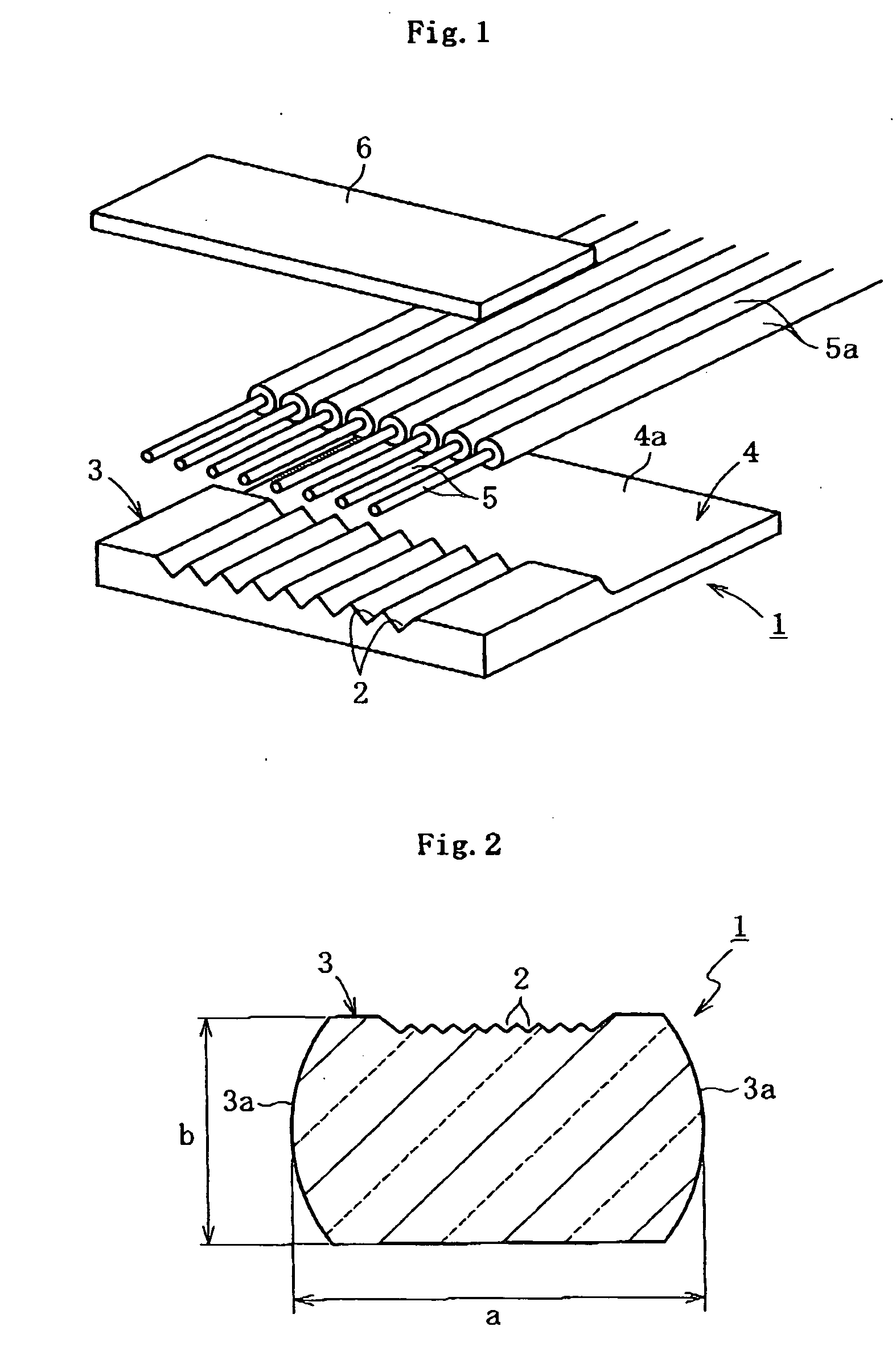
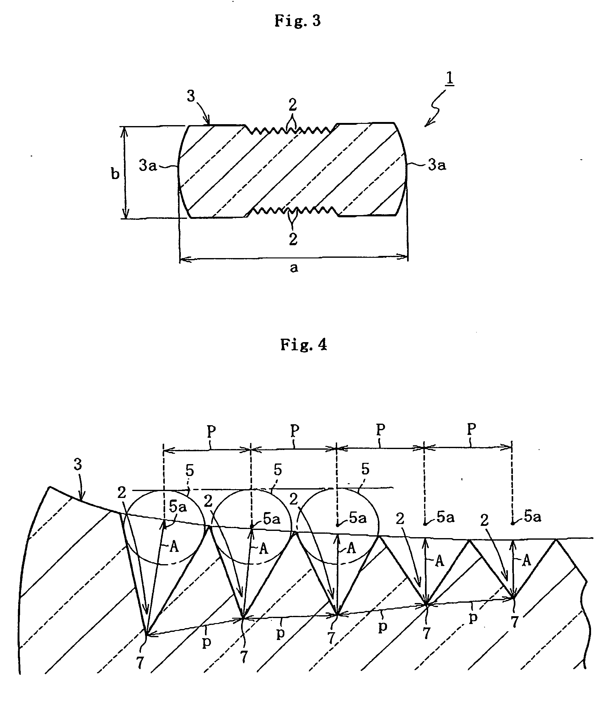
[0059] In Example 1 of the present invention, in order to fabricate an eight-fiber substrate (optical-fiber aligning part) having a widthwise-direction dimension of 4 mm, a thickness-direction dimension of 1 mm, and pitch between each groove of 127 μm, a preliminary preform composed of eight large V-grooves all having the same depth was fabricated, and the preliminary preform was drawn while being heated by the heater such that viscosity reaches 103 to 108 dPa·s. In the obtained optical-fiber aligning part of the substrate, the central axes of the optical fibers arranged in the V-grooves at the center portion was about 0.8 μm lower than those arranged in the V-grooves at both ends thereof in the widthwise direction, as shown by the dotted characteristic curve Ga in FIG. 10. Each deviation amount of the positions of the central axes of the optical fibers arranged in the eight V-grooves is divided by the rate of reduction caused by the drawing, and a preform corrected by only the amou...


PUM


Abstract

An object of the present invention is to very accurately position and align a plurality of optical fibers in each groove of a substrate for an optical fiber array, without leading to inappropriate upsizing and complication of an apparatus and increase in cost To achieve the object, an optical-fiber aligning part 3 of a substrate 1 is formed, in parallel, with a plurality of grooves 2 at least on the top thereof, the plurality of grooves retaining and aligning a plurality of optical fibers 5. A cross section perpendicular to a longitudinal direction of the grooves 2 is recessed at a center portion of the top in the widthwise direction, and depths A of the grooves 2 provided at the center portion are shallower than depths A of the grooves 2 provided at both ends in the widthwise direction.

Description

FIELD OF THE INVENTION [0001] The present invention relates to a substrate for an optical fiber array and a method for fabricating the same, in particular to a substrate for an optical fiber array having an optical-fiber aligning part, which is formed, in parallel, with a plurality of grooves retaining and aligning a plurality of optical fibers, and a method for fabricating the same. BACKGROUND OF THE INVENTION [0002] In recent years, with an increase in capacity, speed or the like of optical communication network, substrate for optical fiber array (hereinafter also referred to as substrate) is frequently being used as component constituting optical splitter which branches one optical fiber into many (e.g., eight) optical fibers, optical branching filter which branches light in each wavelength region, and even optical switch which changes light direction, or the like. Such substrate is made of glass, resin or the like, and has an optical-fiber aligning part on which a plurality of g...

Claims


Application Information

Patent Timeline
IPC IPC(8): G02B6/36
CPCG02B6/3636G02B6/3652G02B6/3692G02B6/3696
Inventor TAKEUCHI, HIROKAZUFUNABIKI, NOBUONAKAJIMA, SOTOHIRO
Owner NIPPON ELECTRIC GLASS CO LTD
Why Eureka
Try Eureka