Scoll fluid machine
a fluid machine and roller technology, applied in the direction of machines/engines, rotary/oscillating piston pump components, liquid fuel engines, etc., can solve the problems of a large amount of power consumption in the power conditioning circuit, affecting the efficiency of the machine, so as to achieve easy control of the capacity and reduce the power required. , the effect of improving efficiency
- Summary
- Abstract
- Description
- Claims
- Application Information
AI Technical Summary
Benefits of technology
Problems solved by technology
Method used
Image
Examples
first embodiment
[0065] First Embodiment
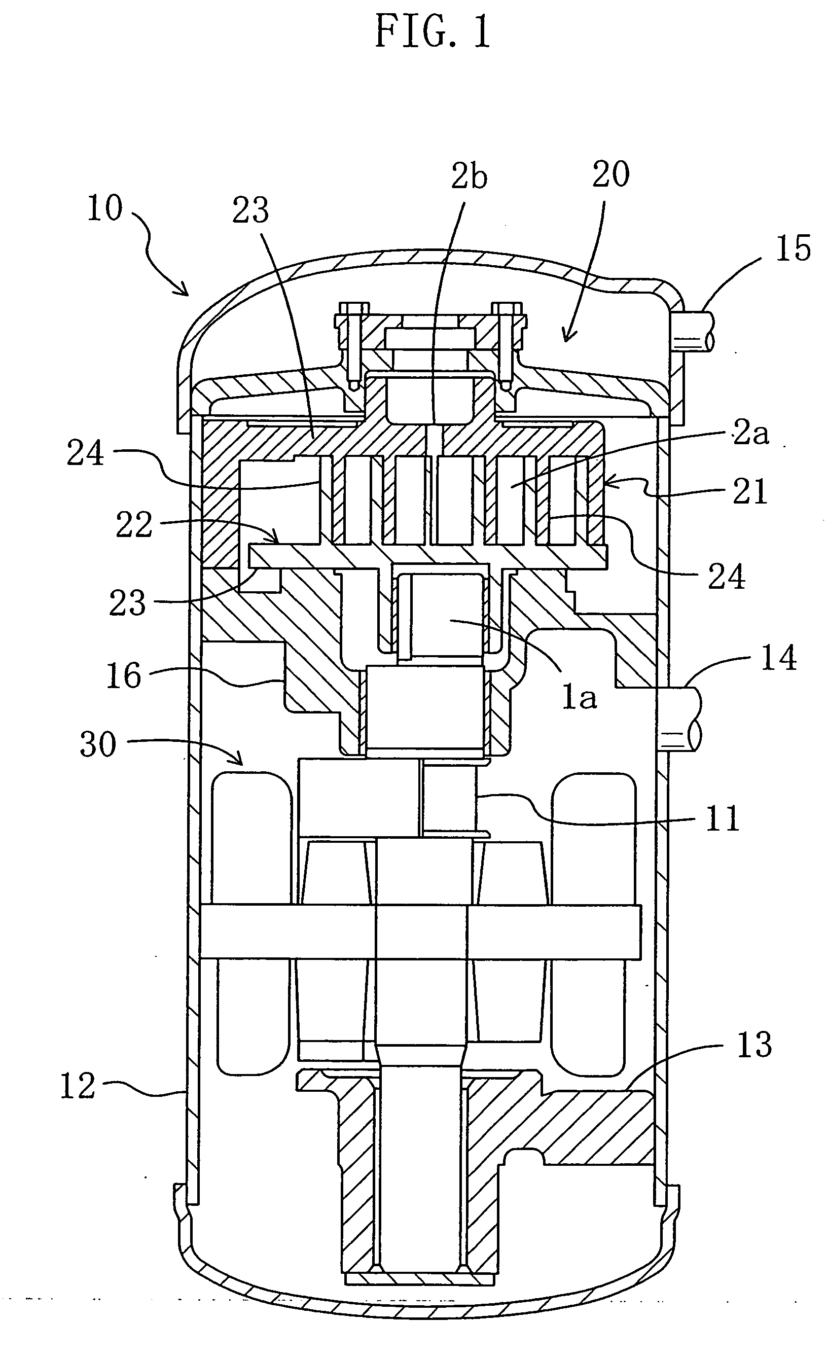
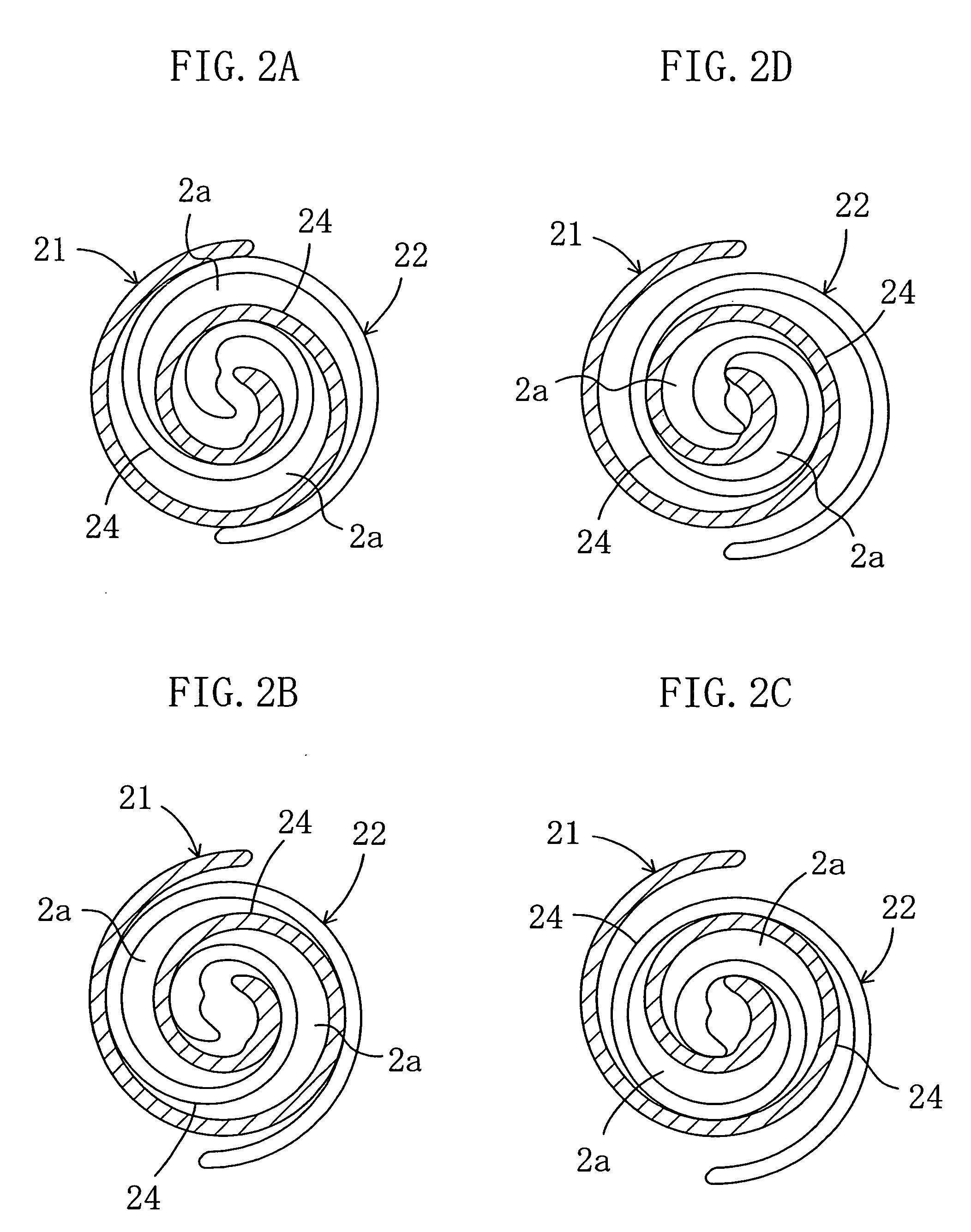
[0066] As shown in FIGS. 1 and 2A to 2D, a scroll fluid machine of the present embodiment is a scroll compressor (10). The scroll compressor (10) includes a compressor mechanism (20), a motor (30) and a drive shaft (11). The scroll compressor (10) is incorporated in a refrigerant circuit such as an air conditioner to compress refrigerant gas.
[0067] The motor (30) is connected to the compressor mechanism (20) via the drive shaft (11). The compressor mechanism (20) and the motor (30) are hermetically disposed in a cylindrical casing (12). The scroll compressor (10) is vertically oriented. The compressor mechanism (20) is positioned at an upper part of the inside space of the casing (12) and a bottom bearing (13) is positioned at a lower part of the inside space of the casing (12). The motor (30) is arranged between the compressor mechanism (20) and the bottom bearing (13).
[0068] The casing (12) further includes a suction pipe (14) provided between the compress...
second embodiment
[0103] Second Embodiment
[0104] Hereinafter, a detailed explanation of the second embodiment will be provided with reference to FIG. 6.
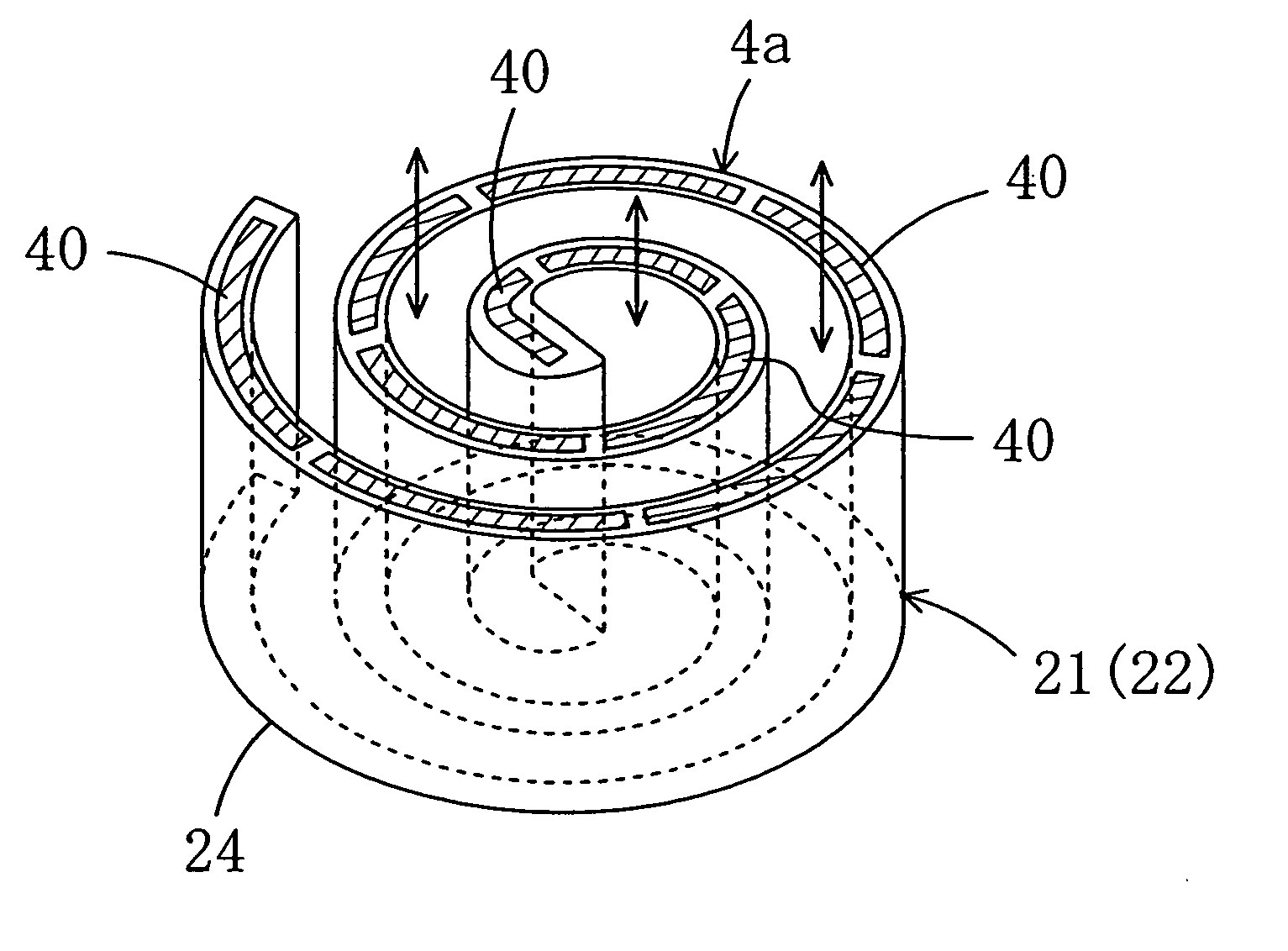
[0105] Different from the polymer actuators (40) of the first embodiment which are configured to change their shapes along the height, the polymer actuators (40) of the present embodiment change their shapes in the circumferential direction.
[0106] Specifically, as indicated by the arrows in FIG. 6, the polymer actuators (40) are configured to change their shapes along the spiral of the wrap (24).
[0107] If all the polymer actuators (40) reach the maximum length during the compression of the refrigerant, gaps between the polymer actuators (40) are minimized, thereby maximizing the compression capacity. If the length of the polymer actuators (40) is reduced from the maximum level at which the capacity is at the maximum, the gaps between the polymer actuators (40) increase, thereby increasing the amount of the space between the end plate (23) and the w...
third embodiment
[0114] Third Embodiment
[0115] A detailed explanation of a third embodiment of the present invention will be provided with reference to FIG. 7.
[0116] Different from the polymer actuator (40) of the first embodiment which also functions as a seal, the polymer actuator (40) of the present embodiment is separated from the seal.
[0117] Specifically, a sealing element (50) is provided on each of the polymer actuators (40) such that the sealing element (50) contacts the end plate (23).
[0118] According to the structure, the wrap (24) and the end plate (23) are sealed with reliability and damage to the polymer actuators (40) is surely prevented.
[0119] Other components and the effect of the present embodiment are the same as those of the first embodiment.
PUM
 Abstract
Description
Claims
Application Information
 - R&D
- Intellectual Property
- Life Sciences
- Materials
- Tech Scout
- Unparalleled Data Quality
- Higher Quality Content
- 60% Fewer Hallucinations
Browse by: Latest US Patents, China's latest patents, Technical Efficacy Thesaurus, Application Domain, Technology Topic, Popular Technical Reports.
© 2025 PatSnap. All rights reserved.Legal|Privacy policy|Modern Slavery Act Transparency Statement|Sitemap|About US| Contact US: help@patsnap.com


