Metal glass body, process for producing the same and apparatus therefor

a technology of metal glass and process, applied in the field of metal glass body, can solve the problems of no other process, limit the size of the resulting member, and the inability to manufacture large sizes with certain alloy systems, and achieve the effect of improving the formation capability of metal glass

Inactive Publication Date: 2007-05-17
NAT INST OF ADVANCED IND SCI & TECH
View PDF1 Cites 16 Cited by
  • Summary
  • Abstract
  • Description
  • Claims
  • Application Information

AI Technical Summary

Benefits of technology

[0014] The present invention achieves the particular effects of (1) allowing a metal glass body to be provided having a metal glass texture structure of microcrystals dispersed uniformly throughout a glass phase, (2) allowing metal glass formation capability to be improved by the application of electromagnetic vibrating force to molten metal, (3) allowing the aforementioned metal glass body to be manufactured by a method which is not dependent on cooling speed, (4) allowing the manufacture of a lightweight, very strong metal member, (5) allowing large-size members to be produced without any restriction on the size of the resulting member, (6) expanding the range of usable metal materials by improving metal glass formation capability, (7) allowing large, bulky raw materials to be obtained because

Problems solved by technology

At present, however, there is no process other than the rapid cooling method.
However, in manufacturing methods that rely on rapid cooling, extremely high cooling speeds are necessary to obtain metal glass with some alloy

Method used


Image

  • Metal glass body, process for producing the same and apparatus therefor
  • Metal glass body, process for producing the same and apparatus therefor
  • Metal glass body, process for producing the same and apparatus therefor

Examples


example 1

[0027] In this invention, an electromagnetic vibration process is explained which uses Mo foil for the holding container.

1) Methods

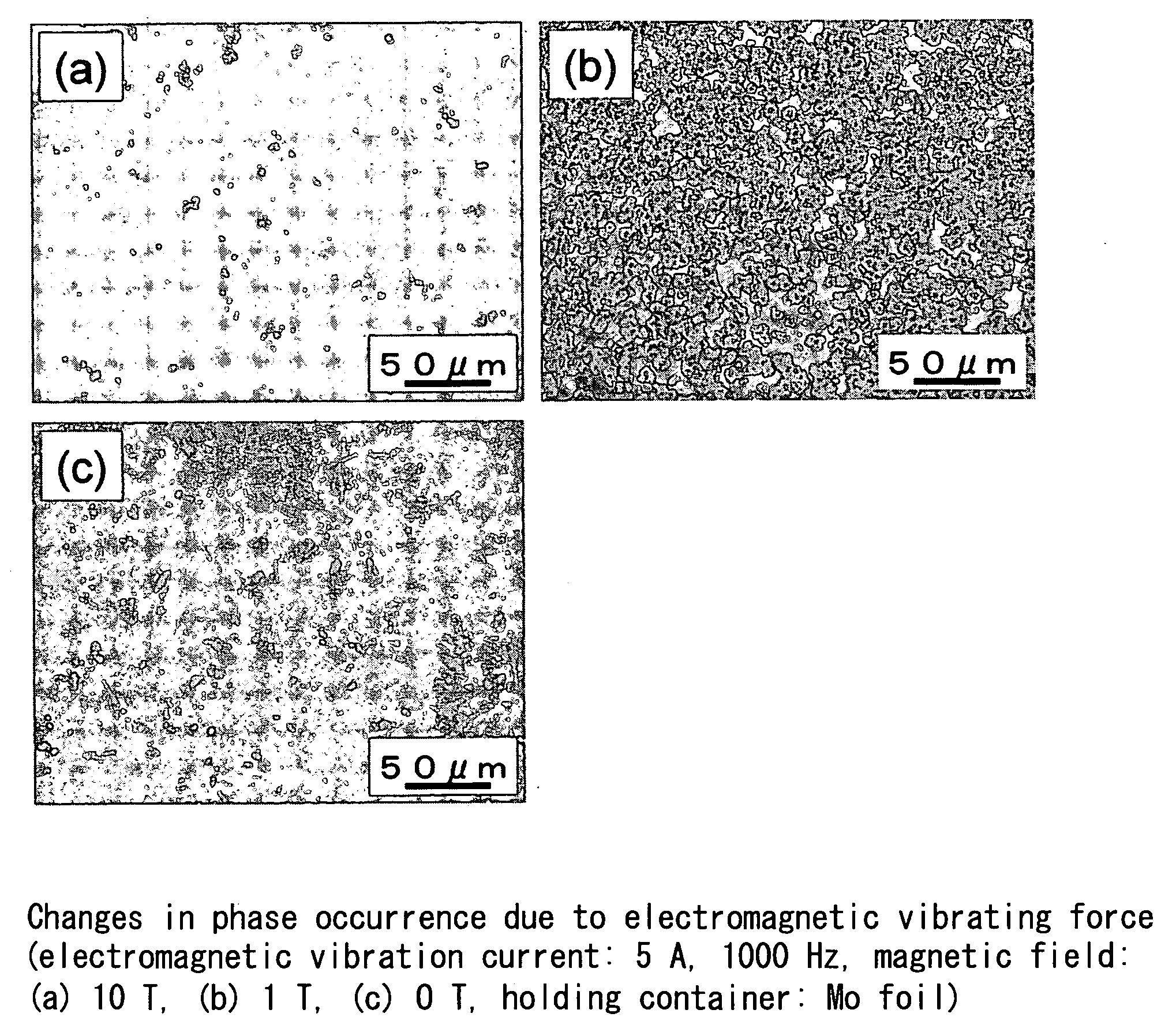
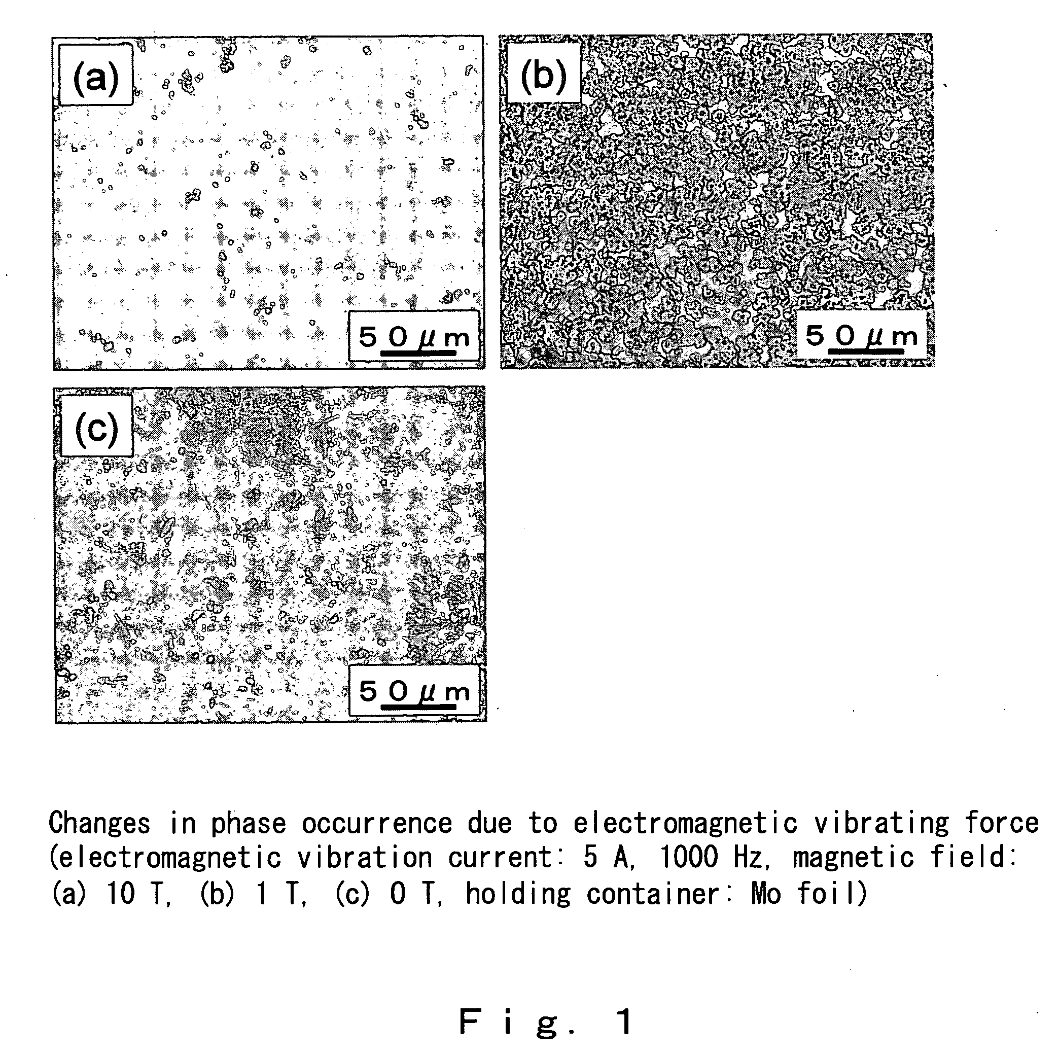
[0028] An electromagnetic vibration-applying mechanism was prepared using Mo foil for the holding container. A Mg65Y10Cu25 (2 mm dia., 12 mm) alloy was placed as the sample in the holding container and heated with an external heater to melt it at 550° C. for 2 minutes, and then electromagnetic vibration was applied thereto for 10 seconds, while spraying water thereon to water-cool the alloy. The effects of the electromagnetic vibrating force on metal glass formation capability were investigated.

2) Effects

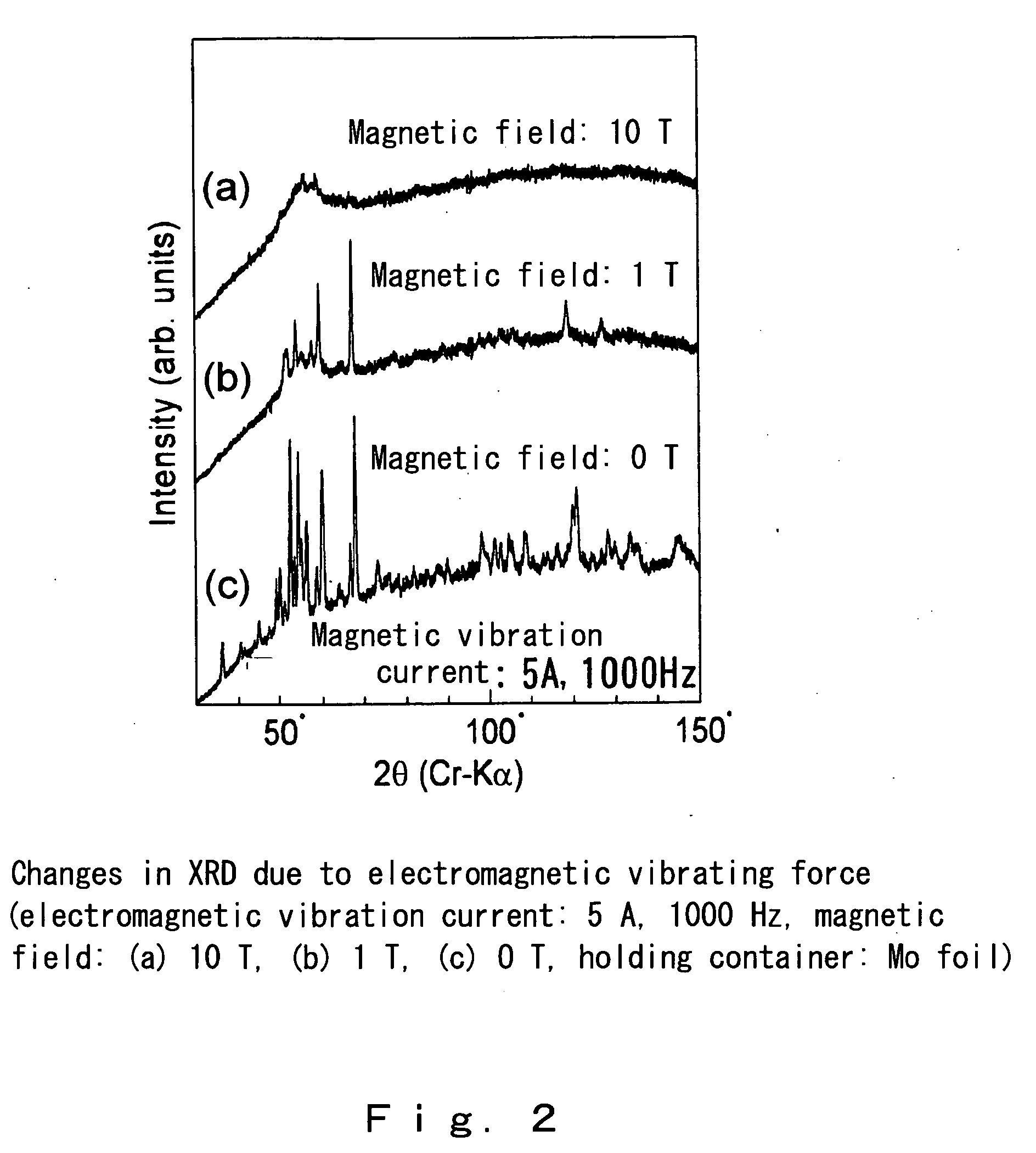
[0029] As shown in the structural photograph of FIG. 1(a) and the XRD of FIG. 2(a), when electromagnetic vibration was applied at an electromagnetic vibrating current of 5 A, 1000 Hz with a magnetic field of 10 T, a metal glass single phase was obtained.

[0030] When the electromagnetic vibrating force was weakened by reducing the magnetic field to ...

example 2

[0031] In this example, an electromagnetic vibrating process is explained which uses an alumina tube for the holding container.

1) Methods

[0032] Using an alumina tube (external diameter 3 mm, internal diameter 2 mm) with a slower cooling speed than Mo foil as the holding container, Mg65Y10Cu25 (2 mm dia., 12 mm) alloy was placed in the container and heated with an external heater to melt it at 550° C. for 2 minutes, and then electromagnetic vibration was applied for 10 seconds, while spraying water thereon to water-cool the alloy. The effects of electromagnetic vibrating force on metal glass formation capability using as the holding container an alumina tube, which has a slower cooling speed was investigated.

2) Effects

[0033]FIG. 3 shows structural photographs when the electromagnetic vibrating force was set to a magnetic field of 10 T and a magnetic vibrating current of 5 A, with the electromagnetic vibrating frequency at 100 Hz, 1000 Hz and 5000 Hz. As shown in FIG. 3(a) at an...

example 3

[0035] In this example, the effects were studied in an alloy system other than Mg.

1) Methods

[0036] To confirm that this process is effective even with metal materials other than Mg65Y10Cu25 alloy, a similar test was performed using (Fe0.6Co0.4)72Si4B20Nb4 alloy, the melting point of which is about 800° C. higher than that of Mg alloy, and the effects of this process were confirmed. The current frequency range was 10 Hz or more, the magnetic field strength range was 1 Tesla or more, and the current strength range was 1×10⁶ A / m2 or more.

2) Results

[0037] The results are shown in FIG. 5. When no electromagnetic vibration was applied, many crystals were generated which could be distinguished by their black color, but when electromagnetic vibration was applied (5 A, 5,000 Hz, 10 T), the crystals were reduced and there was more vitrification. This shows that generation of metal glass by an electromagnetic vibration process is effective even in metal materials other than magnesium all...


PUM

PropertyMeasurementUnit
Magnetic fieldaaaaaaaaaa
Frequencyaaaaaaaaaa
Temperatureaaaaaaaaaa

Abstract

The present invention relates to a metal glass body and to a manufacturing method and apparatus therefor, and the present invention relates to a metal glass body having a specific metal glass texture structure of fine crystals uniformly dispersed throughout a glass phase, to a metal glass body manufacturing method wherein the metal glass body is manufactured by solidifying a molten metal while applying electromagnetic vibrating force thereto to form a metal glass, during which a direct current magnetic field and an alternating current electrical field are applied simultaneously to generate electromagnetic vibration which is exerted on the molten metal, and to an apparatus for manufacturing a metal glass body. According to the present invention, it is possible to provide a method for manufacturing a novel metal glass body which allows mass production of metal glass members which hold promise as lightweight, highly-strong and highly-functional structural members, along with a metal glass body with a novel metal glass texture structure obtained by this method.

Description

TECHNICAL FIELD [0001] The present invention relates to a metal glass body having fine crystals dispersed uniformly throughout the entire sample, and to a method for manufacturing the metal glass body and to an apparatus therefor, and more particularly relates to a method for manufacturing a novel metal glass body whereby a metal glass body having a metal glass texture structure of fine crystals uniformly dispersed throughout a glass phase can be produced by solidifying a molten metal while applying electromagnetic vibrating force thereto, to a novel metal glass body obtained by this method and to the manufacture thereof. In the field of metal glass manufacturing technology, which has conventionally required extremely rapid cooling speeds, the present invention provides a novel technology that allows metal glass, which has great potential as a light, highly-strong and highly-functional structural material, to be mass-produced by a method that is not dependent on cooling speed, and p...

Claims


Application Information

Patent Timeline
IPC IPC(8): C03C15/00B22D27/02
CPCB22D27/02
Inventor MIWA, KENJITAMURA, TAKUYA
Owner NAT INST OF ADVANCED IND SCI & TECH
Why Eureka
Try Eureka